MAIN BODY ECU REMOVAL
CAUTION / NOTICE / HINT
The necessary procedures (adjustment, calibration, initialization, or registration) that must be performed after parts are removed, installed, or replaced during the main body ECU (multiplex network body ECU) removal/installation are shown below.
| Replaced Part or Performed Procedure | Necessary procedures | Effect/Inoperative Function when Necessary Procedure not Performed | Link |
|---|---|---|---|
| Replacement of main body ECU (multiplex network body ECU) | Perform code registration |
|
See Service Bulletin for the registration method. |
PROCEDURE
-
PRECAUTION
Note
-
Do not remove the main body ECU (multiplex network body ECU) except when replacing it.
-
When removing the main body ECU (multiplex network body ECU), always replace it with a new one.
Tech Tips
-
Use the same procedure for RHD and LHD vehicles.
-
The procedure listed below is for LHD vehicles.
-
-
REMOVE LOWER NO. 1 INSTRUMENT PANEL AIRBAG ASSEMBLY
-
REMOVE NO. 1 AIR DUCT SUB-ASSEMBLY
-
REMOVE NO. 1 HEATER TO REGISTER DUCT
-
REMOVE NO. 3 INSTRUMENT PANEL TO COWL BRACE SUB-ASSEMBLY
-
REMOVE INSTRUMENT PANEL JUNCTION BLOCK ASSEMBLY WITH MAIN BODY ECU
-
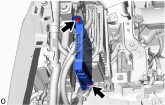
Remove the 2 nuts and disconnect the ECU.
Note
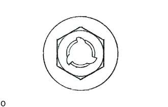
If the removed nut is the same shape as that shown in the illustration, replace it the supplied replacement part.
-
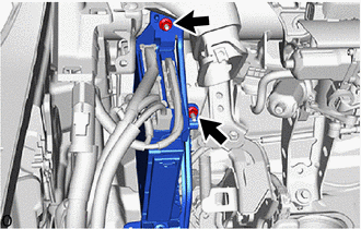
Remove the 2 nuts and disconnect the instrument panel junction block assembly with main body ECU.
Note
If the removed nut is the same shape as that shown in the illustration, replace it the supplied replacement part.
-
Disconnect the 5 connectors.
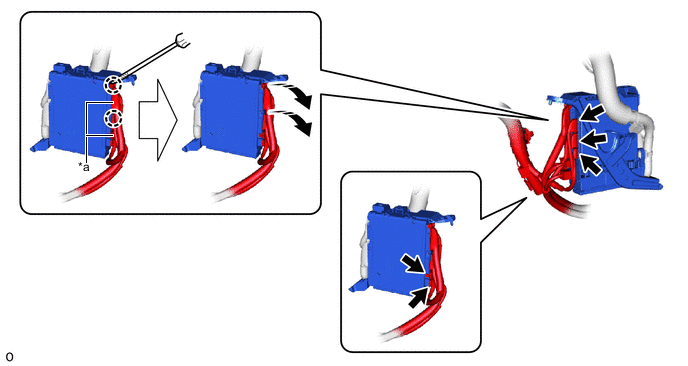
*a Lever Connector - - 
Rotate in this Direction 
Protective Tape -
Using a thin-bladed screwdriver with its tip wrapped with protective tape, detach the claw and disconnect the 2 lever connectors.
-
Detach the clamp.
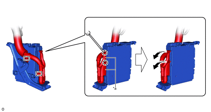
*a Lever Connector - - Rotate in this Direction Protective Tape -
Using a thin-bladed screwdriver with its tip wrapped with protective tape, detach the claw, disconnect the 2 lever connectors and remove the instrument panel junction block with main body ECU assembly.
-
-
REMOVE MAIN BODY ECU (MULTIPLEX NETWORK BODY ECU)
-
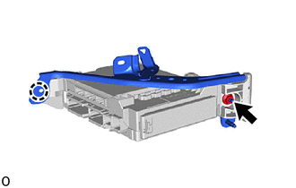
Remove the nut.
Note
If the removed nut is the same shape as that shown in the illustration, replace it the supplied replacement part.
-
Detach the claw and remove the wiring harness clamp bracket.
-
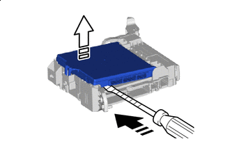
Press the lock of the instrument panel junction block assembly and release the lock of the main body ECU (multiplex network body ECU) as shown in the illustration.
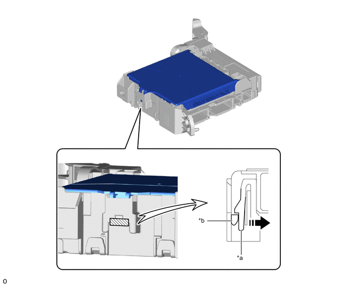
*a Instrument Panel Junction Block Assembly *b Main Body ECU (Multiplex Network Body ECU) Movement Direction Instrument Panel Junction Block Assembly Lock -
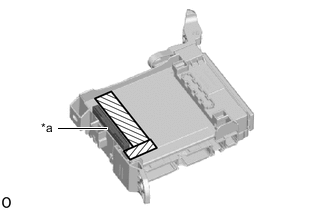
*a Internal Connector Near Internal Connector While pressing the lock, horizontally insert a thin-bladed screwdriver with its tip wrapped with protective tape between the main body ECU (multiplex network body ECU) and instrument panel junction block assembly (near the internal connector).
Note
Use a screwdriver with a diameter between 5.0 mm (0.197 in.) and 6.3 mm (0.248 in.) and a length of approximately 90 mm (3.54 in.).
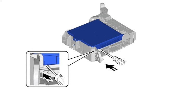
Horizontally Insert a Thin-bladed Screwdriver Protective Tape -
Insert a Thin-bladed Screwdriver in this Direction 
Released in this Direction Protective Tape When the thin-bladed screwdriver with its tip wrapped with protective tape is inserted, the internal connector lock is released.
Note
Replace the instrument panel junction block assembly when the connector terminal, the locking section, or the case is damaged or deformed.
-
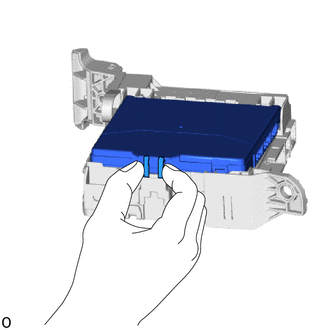
Hold the rib of the main body ECU (multiplex network body ECU).
-
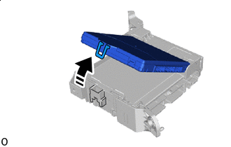
Rotate in this Direction While rotating the main body ECU (multiplex network body ECU), completely release the lock.
-
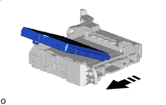
Remove in this Direction Remove the main body ECU (multiplex network body ECU) from the instrument panel junction block assembly.
-