PRE-CRASH SAFETY SYSTEM Pre-crash Safety Brake Cancel Switch Circuit
DESCRIPTION
The driving support ECU receives pre-crash brake on/off signals from the pre-crash brake cancel switch.
WIRING DIAGRAM
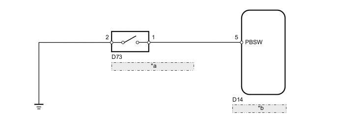
| *a | Pre-crash Brake Cancel Switch |
| *b | Driving Support ECU |
PROCEDURE
-
READ VALUE USING INTELLIGENT TESTER (PRE-CRASH BRAKE CANCEL SWITCH)
-
Use the Data List to check if the pre-crash brake cancel switch is functioning properly.
Pre-Crash 2 Tester Display Measurement Item/Range Normal Condition Diagnostic Note Pre-Crash Brake OFF Switch Pre-crash brake cancel switch signal / ON or OFF ON: Pre-crash brake cancel switch on
OFF: Pre-crash brake cancel switch off
- OK On screen, each item changes between ON and OFF according to above chart.
OK 
PROCEED TO NEXT SUSPECTED AREA SHOWN IN PROBLEM SYMPTOMS TABLE Click here
NG 
-
-
INSPECT PRE-CRASH BRAKE CANCEL SWITCH
-
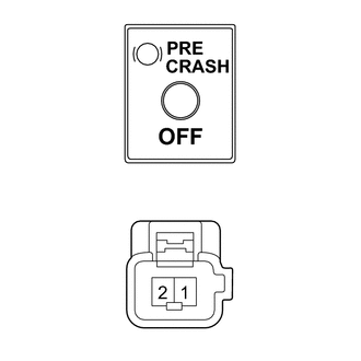
Remove the pre-crash brake cancel switch Click here.
-
Measure the resistance according to the value(s) in the table below.
Standard Resistance Tester Connection Switch Condition Specified Condition 1 - 2 Pressed Below 1 Ω Not pressed 10 kΩ or higher
NG
REPLACE PRE-CRASH BRAKE CANCEL SWITCH Click here
OK
-
-
CHECK HARNESS AND CONNECTOR (PRE-CRASH BRAKE CANCEL SWITCH - DRIVING SUPPORT ECU AND BODY GROUND)
-
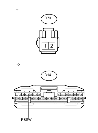
Text in Illustration *1 Front view of wire harness connector
(to Pre-crash Brake Cancel Switch)
*2 Front view of wire harness connector
(to Driving Support ECU)
Disconnect the D73 switch connector.
-
Disconnect the D14 ECU connector.
-
Measure the resistance according to the value(s) in the table below.
Standard Resistance Tester Connection Condition Specified Condition D73-1 - D14-5 (PBSW) Always Below 1 Ω D73-2 - Body ground D73-1 - Body ground Always 10 kΩ or higher Result Result Proceed to OK (for LHD) A OK (for RHD) B NG C
A
REPLACE DRIVING SUPPORT ECU Click here
B
REPLACE DRIVING SUPPORT ECU Click here
C
REPAIR OR REPLACE HARNESS OR CONNECTOR
-