REAR WHEEL ALIGNMENT(for Torsion Beam Type Suspension) INSPECTION
PROCEDURE
INSPECT TIRES
MEASURE VEHICLE HEIGHT
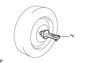
INSPECT CAMBER
Note:Inspect while the vehicle is unloaded.
-
*a
Camber-caster-kingpin Gauge
Install a camber-caster-kingpin gauge.
Inspect the camber.
Camber (Unloaded Vehicle)
-
Engine
Tire Size
Camber Inclination
Right-left Difference
for Hatchback
1ND-TV
195/65R15
205/55R16
-1°28' +/- 0°30' (-1.47° +/-0.50°)
-1°24' +/- 0°30' (-1.40° +/-0.50°)*a
0°30' (0.50°) or less
215/45R17
-1°28' +/- 0°30' (-1.47° +/-0.50°)
1NR-FE
195/65R15
205/55R16
-1°28' +/- 0°30' (-1.47° +/-0.50°)
-1°24' +/- 0°30' (-1.40° +/-0.50°)*a
215/45R17
-1°28' +/- 0°30' (-1.47° +/-0.50°)
for Wagon
1ND-TV
195/65R15
205/55R16
215/45R17
-1°27' +/- 0°30' (-1.45° +/-0.50°)
1NR-FE
195/65R15
205/55R16
215/45R17
-1°27' +/- 0°30' (-1.45° +/-0.50°)
for Sedan
1ZR-FAE
1ZR-FE
195/65R15
205/55R16
-1°28' +/- 0°30' (-1.47° +/-0.50°)
-1°24' +/- 0°30' (-1.40° +/-0.50°)*a
215/45R17
-1°28' +/- 0°30' (-1.47° +/-0.50°)
2ZR-FE
195/65R15
205/55R16
-1°28' +/- 0°30' (-1.47° +/-0.50°)
-1°24' +/- 0°30' (-1.40° +/-0.50°)*a
1NR-FE
195/65R15
205/55R16
-1°28' +/- 0°30' (-1.47° +/-0.50°)
-1°24' +/- 0°30' (-1.40° +/-0.50°)*a
215/45R17
-1°28' +/- 0°30' (-1.47° +/-0.50°)
1ND-TV
195/65R15
205/55R16
-1°28' +/- 0°30' (-1.47° +/-0.50°)
-1°24' +/- 0°30' (-1.40° +/-0.50°)*a
215/45R17
-1°28' +/- 0°30' (-1.47° +/-0.50°)
*a: for Rough Road Package
Tip:Camber is not adjustable. If the measurement is not within the specified range, inspect the suspension parts for damage and/or wear, and replace them if necessary.
-
INSPECT TOE-IN
Note:Inspect while the vehicle is unloaded.
Bounce the vehicle up and down at the corners to stabilize the suspension.
Release the parking brake and move the shift lever to N (for Multi-mode Manual Transaxle).
Release the parking brake and move the shift lever to neutral (for Manual Transaxle).
Push the vehicle straight ahead approximately 5 m (16.4 ft.). (Step A)
-
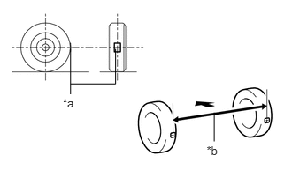
*a
Tread Center Mark
*b
Dimension B

Front of the Vehicle
Put tread center marks on the rearmost points of the rear wheels and measure the distance between the marks (dimension B).
Slowly push the vehicle straight ahead to cause the rear wheels to rotate 180°. Use the rear tire valve as a reference point.
Tip:Do not allow the wheels to rotate more than 180°. If the wheels rotate more than 180°, perform the procedure from step A again.
-
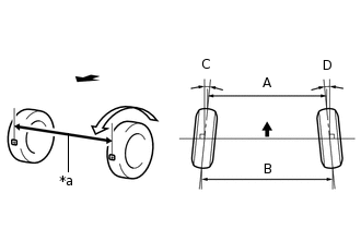
*a
Dimension A
Front of the Vehicle
Measure the distance between the tread center marks on the front of the rear wheels (dimension A).
Toe-in (Unloaded Vehicle)
Engine
Specified Condition
Right-left Difference
for Hatchback
1ND-TV
C + D: 0°15' +/- 0°16' (0.25° +/- 0.27°)
C + D: 0°06' +/- 0°16' (0.10° +/- 0.27°)*a
0°45' (0.75°) or less
B - A: 2.9 +/- 3.0 mm (0.114 +/- 0.118 in.)
B - A: 1.2 +/- 3.0 mm (0.0472 +/- 0.118 in.)*a
-
1NR-FE
C + D: 0°15' +/- 0°16' (0.25° +/- 0.27°)
C + D: 0°06' +/- 0°16' (0.10° +/- 0.27°)*a
0°45' (0.75°) or less
B - A: 2.9 +/- 3.0 mm (0.114 +/- 0.118 in.)
B - A: 1.2 +/- 3.0 mm (0.0472 +/- 0.118 in.)*a
-
for Wagon
1ND-TV
C + D: 0°13' +/- 0°16' (0.22° +/- 0.27°)
0°45' (0.75°) or less
B - A: 2.7 +/- 3.0 mm (0.106 +/- 0.118 in.)
-
1NR-FE
C + D: 0°14' +/- 0°16' (0.23° +/- 0.27°)
0°45' (0.75°) or less
B - A: 2.8 +/- 3.0 mm (0.110 +/- 0.118 in.)
-
for Sedan
1ZR-FAE
1ZR-FE
2ZR-FE
1NR-FE
1ND-TV
C + D: 0°15' +/- 0°16' (0.26° +/- 0.27°)
C + D: 0°06' +/- 0°16' (0.11° +/- 0.27°)*a
0°45' (0.75°) or less
B - A: 2.9 +/- 3.0 mm (0.114 +/- 0.118 in.)
B - A: 1.2 +/- 3.0 mm (0.0472 +/- 0.118 in.)*a
-
*a: for Rough Road Package
Tip:Measure "B - A" only when "C + D" cannot be measured.
If the toe-in is not within the specified range, inspect the suspension parts and replace them if necessary.