MONOLITHIC CONVERTER(for DPF) INSTALLATION
PROCEDURE
INSTALL NO. 2 MANIFOLD CONVERTER INSULATOR
Install the No. 2 manifold converter insulator with the 3 bolts.
29 N*m
291 kgf*cm
21 ft.*lbf
INSTALL NO. 2 VACUUM PIPE
Temporarily install the No. 2 vacuum pipe with the union nut and bolt.
Tighten the bolt.
25 N*m
255 kgf*cm
18 ft.*lbf
Using a 14 mm union nut wrench, tighten the union nut of the No. 2 vacuum pipe.
30 N*m
306 kgf*cm
22 ft.*lbf
Note:Use the formula to calculate special torque values for situations where a union nut wrench is click here combined with a torque wrench.
INSTALL NO. 1 VACUUM PIPE
Temporarily install the No. 1 vacuum pipe with the union nut and bolt.
Tighten the bolt.
25 N*m
255 kgf*cm
18 ft.*lbf
Using a 17 mm union nut wrench, tighten the union nut of the No. 1 vacuum pipe.
48 N*m
489 kgf*cm
35 ft.*lbf
Note:Use the formula to calculate special torque values for situations where a union nut wrench is click here combined with a torque wrench.
INSTALL EXHAUST GAS TEMPERATURE SENSOR
INSTALL NO. 2 EXHAUST GAS TEMPERATURE SENSOR
INSTALL NO. 2 VACUUM TRANSMITTING HOSE ASSEMBLY
-
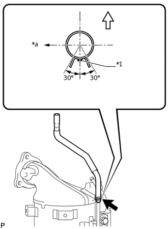
*1
Paint Mark (Green)
*a
LH Side

Front Side of The Vehicle
Install the No. 2 vacuum transmitting hose assembly to the No. 2 vacuum pipe, and slide the clamp to secure the hose.
Tip:The direction of the hose clamp is indicated in the illustration.
-
INSTALL VACUUM TRANSMITTING HOSE ASSEMBLY
-
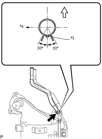
*1
Paint Mark (Light Blue)
*a
LH Side
Front Side of The Vehicle
Install the vacuum transmitting hose assembly to the No. 1 vacuum pipe, and slide the clamp to secure the hose.
Tip:The direction of the hose clamp is indicated in the illustration.
-
INSTALL EXHAUST MANIFOLD CONVERTER SUB-ASSEMBLY
Install a new gasket to the turbocharger sub-assembly.
Tip: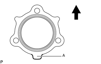

Top
Make sure that the part labeled A is facing downwards as shown in the illustration.
-
Temporarily install the exhaust manifold converter sub-assembly with the 3 new nuts.
-
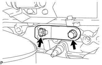
Temporarily install the No. 2 exhaust manifold stay with the 2 bolts and nut.
-
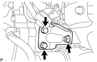
Temporarily install the No. 2 manifold stay with the 3 bolts.
-
Temporarily install the manifold stay with the bolt and nut.
-
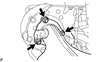
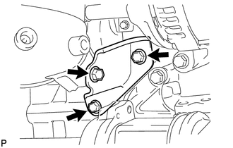
Tighten the 2 bolts of the No. 2 exhaust manifold stay in the order shown in the illustration.
56 N*m
571 kgf*cm
41 ft.*lbf
Tighten the 3 nuts of the exhaust manifold converter sub-assembly.
25 N*m
255 kgf*cm
18 ft.*lbf
Note:Tighten the nuts while pressing the exhaust manifold converter sub-assembly against the engine.
-
Tighten the nut of the No. 2 exhaust manifold stay.
56 N*m
571 kgf*cm
41 ft.*lbf
-
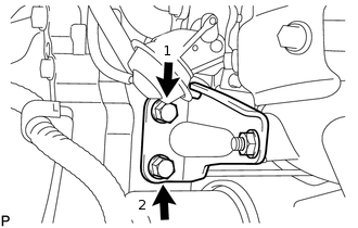
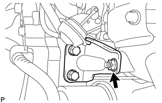
Tighten the bolt of the No. 2 manifold stay shown in the illustration.
56 N*m
571 kgf*cm
41 ft.*lbf
Note:Tighten the bolt while pressing the No. 2 manifold stay against the exhaust manifold converter sub-assembly and cylinder block sub-assembly.
-
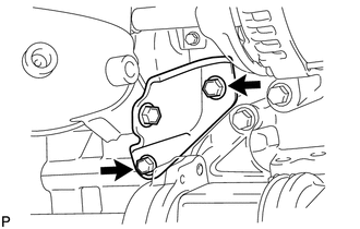
Tighten the 2 bolts of the No. 2 manifold stay shown in the illustration.
56 N*m
571 kgf*cm
41 ft.*lbf
-
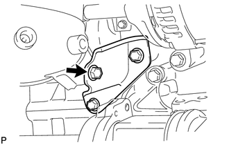
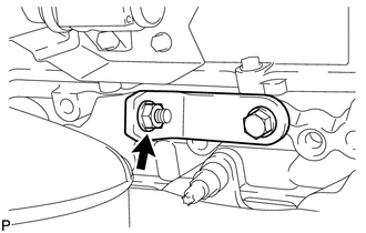
Tighten the bolt of the manifold stay.
25 N*m
255 kgf*cm
18 ft.*lbf
Note:Tighten the bolt while pressing the manifold stay against the exhaust manifold converter sub-assembly and cylinder block sub-assembly.
-
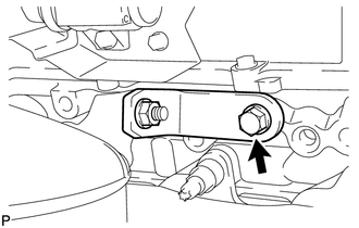
Tighten the nut of the manifold stay.
25 N*m
255 kgf*cm
18 ft.*lbf
Connect the exhaust temperature sensor connector and No. 2 exhaust temperature sensor connector.
INSTALL NO. 1 MANIFOLD CONVERTER INSULATOR
Install the No. 1 manifold converter insulator with the 5 bolts.
29 N*m
291 kgf*cm
21 ft.*lbf
INSTALL ENGINE ASSEMBLY
PERFORM CATALYST RECORD OF DPF THERMAL DETERIORATION CLEAR FUNCTION