SEAT VIBRATION SYSTEM Rear Air Massage Function does not Operate
DESCRIPTION
The rear power seat switch (rear multi operation panel) sends switch operation signals to the position control ECU assembly via LIN communication. The position control ECU assembly that receives the signals operates the refresh seat functions by controlling the seat check valve, lumbar support pump and rear seatback heater.
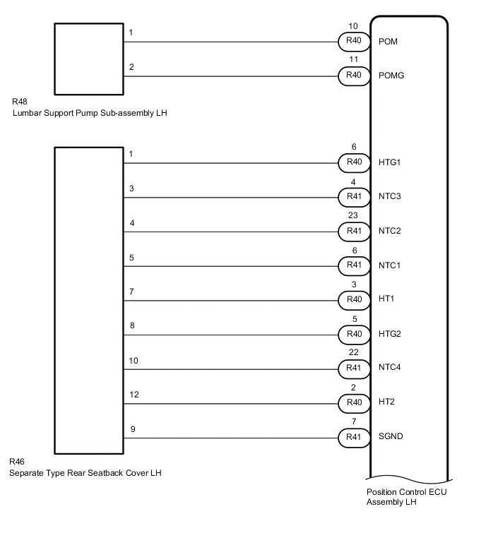
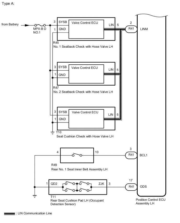
WIRING DIAGRAM
Figure 1. RH Seat:
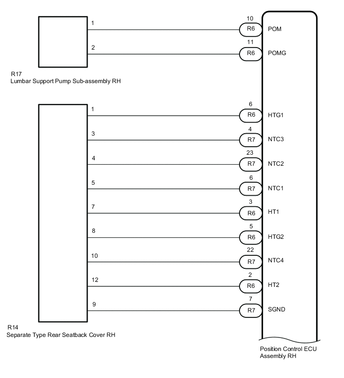

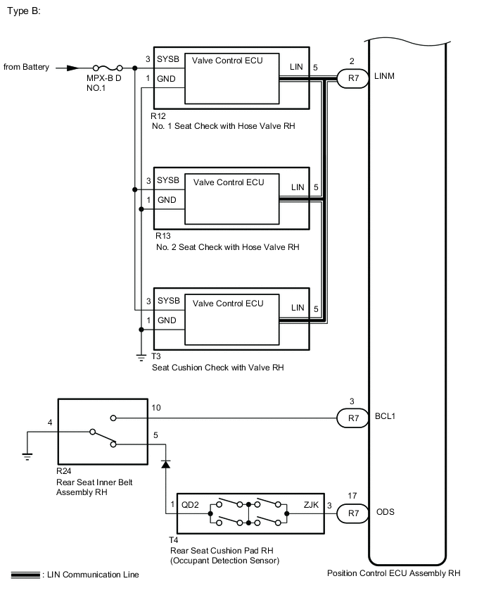
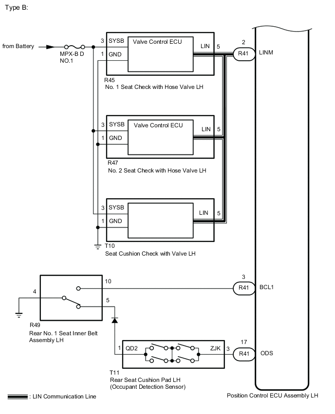
Figure 2. LH Seat:
CAUTION / NOTICE / HINT
Note
-
The seat vibration system uses the LIN communication system. First, confirm that there are no malfunctions in the LIN communication system. Refer to How to Proceed with Troubleshooting.
-
Initializing the position control ECU assembly will clear the seat position memory.
-
Inspect the fuses for circuits related to this system before performing the following procedure.
Tech Tips
Make sure to initialize the position control ECU assembly after replacing the seat assembly or any related parts (including removal and installation).
PROCEDURE
-
CHECK MALFUNCTIONING PARTS
-
Check the problem symptoms.
Result Result Proceed to Rear seat RH malfunctioning A Rear seat LH malfunctioning B
B 
CHECK MALFUNCTIONING PARTS, COMPONENT AND AREA Click here
A 
-
-
CHECK MALFUNCTIONING PARTS, COMPONENT AND AREA
-
Check that each function of the refreshing seat operates normally.
Result Result Proceed to All refreshing functions do not operate A One or more refreshing functions do not operate B
B
PERFORM ACTIVE TEST USING GTS Click here
A
-
-
READ VALUE USING GTS (REAR BUCKLE SWITCH, OCCUPANT SENSOR, RELAXTION SWITCH SIGNAL)
-
Connect the GTS to the DLC3.
-
Turn the engine switch on (IG).
-
Turn the GTS on.
-
Enter the following menus: Body Electrical / Rear Right Seat / Data List.
-
Read the Data List according to the display on the GTS.
Body Electrical > Rear Right Seat > Data ListTester Display Measurement Item Range Normal Condition Diagnostic Note Rear Buckle Switch Rear RH seat belt signal ON/OFF ON: Rear RH seat belt fastened
OFF: Rear RH seat belt unfastened
- Occupant Sensor Occupant detection sensor signal ON/OFF ON: Rear RH seat occupied
OFF: Rear RH seat not occupied
- Relaxation Switch Signal Relaxation switch signal ON/OFF ON: Touch "Relaxation"
OFF: Not touch "Relaxation"
-
Body Electrical > Rear Right Seat > Data ListTester Display Rear Buckle Switch Occupant Sensor Relaxation Switch Signal OK ON or OFF is displayed on the GTS according to the table above. Result Result Proceed to OK A NG (Item: Rear Buckle Switch) B NG (Item: Occupant Sensor) C NG (Item: Relaxation Switch Signal) D
B
INSPECT REAR SEAT INNER BELT ASSEMBLY RH Click here
C
INSPECT REAR SEAT CUSHION PAD RH (OCCUPANT DETECTION SENSOR) Click here
D 
GO TO REAR MULTI OPERATION PANEL SYSTEM
A
-
-
INSPECT LUMBAR SUPPORT PUMP SUB-ASSEMBLY RH
-
Remove the lumbar support pump sub-assembly RH.
-
Inspect the lumbar support pump sub-assembly RH.
Result Proceed to OK NG
NG
REPLACE LUMBAR SUPPORT PUMP SUB-ASSEMBLY RH Click here
OK
-
-
CHECK HARNESS AND CONNECTOR (POSITION CONTROL ECU ASSEMBLY RH - LUMBAR SUPPORT PUMP SUB-ASSEMBLY RH)
-
Disconnect the R6 position control ECU assembly RH connector.
-
Disconnect the R17 lumbar support pump sub-assembly RH connector.
-
Measure the resistance according to the value(s) in the table below.
Standard Resistance Tester Connection Condition Specified Condition R6-10 (POM) - R17-1 Always Below 1 Ω R6-11 (POMG) - R17-2 Always Below 1 Ω R6-10 (POM) or R17-1 - Other terminals and body ground Always 10 kΩ or higher R6-11 (POMG or R17-2 - Other terminals and body ground Always 10 kΩ or higher Result Proceed to OK NG
NG
REPAIR OR REPLACE HARNESS OR CONNECTOR
OK
-
-
CHECK HARNESS AND CONNECTOR (SEAT CHECK VALVE RH - BATTERY AND BODY GROUND)
-
Disconnect the R12 No. 1 seatback check with hose valve RH connector.
-
Disconnect the R13 No. 2 seatback check with hose valve RH connector.
-
Disconnect the T3 seat cushion check with hose valve RH connector.
-
Measure the resistance according to the value(s) in the table below.
Standard Resistance Tester Connection Condition Specified Condition R12-1 (GND) - Body ground Always Below 1 Ω R13-1 (GND) - Body ground Always Below 1 Ω T3-1 (GND) - Body ground Always Below 1 Ω -
Measure the voltage according to the value(s) in the table below.
Standard Voltage Tester Connection Condition Specified Condition R12-3 (SYSB) - Body ground Always 11 to 14 V R13-3 (SYSB) - Body ground Always 11 to 14 V T3-3 (SYSB) - Body ground Always 11 to 14 V Result Proceed to OK NG
NG
REPAIR OR REPLACE HARNESS OR CONNECTOR
OK
-
-
CHECK HARNESS AND CONNECTOR (POSITION CONTROL ECU ASSEMBLY RH - SEAT CHECK VALVE RH)
-
Disconnect the R6 No. 1 position control ECU assembly RH connector.
-
Disconnect the R12 No. 1 seatback check with hose valve RH connector.
-
Disconnect the R13 No. 2 seatback check with hose valve RH connector.
-
Disconnect the T3 seat cushion check with hose valve RH connector.
-
Disconnect the R11 seatback check with bracket valve RH connector.
-
Measure the resistance according to the value(s) in the table below.
Standard Resistance Tester Connection Condition Specified Condition R41-2 (LINM) - R12-5 (LIN) Always Below 1 Ω R41-2 (LINM) - R13-5 (LIN) Always Below 1 Ω R41-2 (LINM) - T3-5 (LIN) Always Below 1 Ω R41-2 (LINM) or R12-5 (LIN) - Other terminals and body ground Always 10 kΩ or higher R41-2 (LINM) or R13-5 (LIN) - Other terminals and body ground Always 10 kΩ or higher R41-2 (LINM) or T3-5 (LIN) - Other terminals and body ground Always 10 kΩ or higher Result Proceed to OK NG
OK
REPLACE POSITION CONTROL ECU ASSEMBLY RH Click here
NG
REPAIR OR REPLACE HARNESS OR CONNECTOR
-
-
INSPECT REAR SEAT INNER BELT ASSEMBLY RH
-
Remove the rear seat inner belt assembly RH.
-
Inspect the rear seat inner belt assembly RH.
Result Proceed to OK NG
NG
REPLACE REAR SEAT INNER BELT ASSEMBLY RH Click here
OK
-
-
CHECK HARNESS AND CONNECTOR (REAR SEAT INNER BELT ASSEMBLY RH - POSITION CONTROL ECU ASSEMBLY RH)
-
Disconnect the R24 rear seat inner belt assembly RH connector.
-
Disconnect the R7 position control ECU assembly RH connector.
-
Measure the resistance according to the value(s) in the table below.
Standard Resistance Tester Connection Condition Specified Condition R24-10 - R7-3 (BCL1) Always Below 1 Ω R24-4 - Body ground Always Below 1 Ω R24-10 or R7-3 (BCL1) - Other terminals and body ground Always 10 kΩ or higher Result Proceed to OK NG
OK
REPLACE POSITION CONTROL ECU ASSEMBLY RH Click here
NG
REPLACE REAR SEAT INNNER BELT ASSEMBLY RH Click here
-
-
INSPECT REAR SEAT CUSHION PAD RH (OCCUPANT DETECTION SENSOR)
-
Remove the rear seat cushion pad RH (occupant detection sensor).
-
Inspect the rear seat cushion pad RH (occupant detection sensor).
Result Proceed to OK NG
NG
REPLACE REAR SEAT CUSHION PAD RH Click here
OK
-
-
CHECK HARNESS AND CONNECTOR (REAR SEAT CUSHION PAD RH - POSITION CONTROL ECU ASSEMBLY RH)
-
Disconnect the T4 rear seat cushion pad RH connector.
-
Disconnect the R7 position control ECU assembly RH connector.
-
Measure the resistance according to the value(s) in the table below.
Standard Resistance Tester Connection Condition Specified Condition T4-3 (ZJK) - R7-17 (ODS) Always Below 1 Ω T4-1 (QD2) - Body ground Always Below 1 Ω T4-3 (ZJK) or R7-17 (ODS) - Other terminals and body ground Always 10 kΩ or higher Result Proceed to OK NG
OK
REPLACE POSITION CONTROL ECU ASSEMBLY RH Click here
NG
REPLACE REAR SEAT INNNER BELT ASSEMBLY RH Click here
-
-
PERFORM ACTIVE TEST USING GTS
-
Connect the GTS to the DLC3.
-
Turn the engine switch on (IG).
-
Turn the GTS on.
-
Enter the following menus: Body Electrical / Rear Right Seat / Active Test.
-
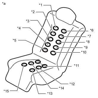
*a Example *1 BR5 *2 BR4 *3 BR3 *4 BR2 *5 BR1 *6 BL5 *7 BL4 *8 BL3 *9 BL2 *10 BL1 *11 C5 *12 C2 *13 C1 *14 C4 *15 C3 Perform the Active Test according to the display on the GTS.
Body Electrical > Rear Right Seat > Active TestTester Display Measurement Item Control Range Diagnostic Note Refresh BL1 Seatback bladder assembly OFF/ON - Refresh BL2 Seatback bladder assembly OFF/ON - Refresh BL3 Seatback bladder assembly OFF/ON - Refresh BL4 Seatback bladder assembly OFF/ON - Refresh BL5 Seatback bladder assembly OFF/ON - Refresh BR1 Seatback bladder assembly OFF/ON - Refresh BR2 Seatback bladder assembly OFF/ON - Refresh BR3 Seatback bladder assembly OFF/ON - Refresh BR4 Seatback bladder assembly OFF/ON - Refresh BR5 Seatback bladder assembly OFF/ON - Refresh C1 Seat cushion bladder assembly OFF/ON - Refresh C2 Seat cushion bladder assembly OFF/ON - Refresh C5 Seat cushion bladder assembly OFF/ON - Refresh C4 Seat cushion bladder assembly OFF/ON - Refresh C3 Seat cushion bladder assembly OFF/ON -
Body Electrical > Rear Right Seat > Active TestTester Display Refresh BL1
Body Electrical > Rear Right Seat > Active TestTester Display Refresh BL2
Body Electrical > Rear Right Seat > Active TestTester Display Refresh BL3
Body Electrical > Rear Right Seat > Active TestTester Display Refresh BL4
Body Electrical > Rear Right Seat > Active TestTester Display Refresh BL5
Body Electrical > Rear Right Seat > Active TestTester Display Refresh BR1
Body Electrical > Rear Right Seat > Active TestTester Display Refresh BR2
Body Electrical > Rear Right Seat > Active TestTester Display Refresh BR3
Body Electrical > Rear Right Seat > Active TestTester Display Refresh BR4
Body Electrical > Rear Right Seat > Active TestTester Display Refresh BR5
Body Electrical > Rear Right Seat > Active TestTester Display Refresh C1
Body Electrical > Rear Right Seat > Active TestTester Display Refresh C2
Body Electrical > Rear Right Seat > Active TestTester Display Refresh C5
Body Electrical > Rear Right Seat > Active TestTester Display Refresh C4
Body Electrical > Rear Right Seat > Active TestTester Display Refresh C3 Result Proceed NEXT
NEXT
CHECK REFRESHING SEAT Click here
CHECK REFRESHING SEAT Click here
CHECK REFRESHING SEAT Click here -
-
CHECK MALFUNCTIONING PARTS, COMPONENT AND AREA
-
Check that each function of the refreshing seat operates normally.
Result Result Proceed to All refreshing functions do not operate A One or more refreshing functions do not operate B
B
PERFORM ACTIVE TEST USING GTS Click here
A
-
-
READ VALUE USING GTS (REAR BUCKLE SWITCH, OCCUPANT SENSOR, RELAXTION SWITCH SIGNAL)
-
Connect the GTS to the DLC3.
-
Turn the engine switch on (IG).
-
Turn the GTS on.
-
Enter the following menus: Body Electrical / Rear Left Seat / Data List.
-
Read the Data List according to the display on the GTS.
Body Electrical > Rear Left Seat > Data ListTester Display Measurement Item Range Normal Condition Diagnostic Note Rear Buckle Switch Rear LH seat belt signal ON/OFF ON: Rear LH seat belt fastened
OFF: Rear LH seat belt unfastened
- Occupant Sensor Occupant detection sensor signal ON/OFF ON: Rear LH seat occupied
OFF: Rear LH seat not occupied
- Relaxation Switch Signal Relaxation switch signal ON/OFF ON: Touch "Relaxation"
OFF: Not touch "Relaxation"
-
Body Electrical > Rear Left Seat > Data ListTester Display Rear Buckle Switch Occupant Sensor Relaxation Switch Signal OK ON or OFF is displayed on the GTS according to the table above. Result Result Proceed to OK A NG (Item: Rear Buckle Switch) B NG (Item: Occupant Sensor) C NG (Item: Relaxation Switch Signal) D
B
INSPECT REAR SEAT INNER BELT ASSEMBLY LH Click here
C
INSPECT REAR SEAT CUSHION PAD LH (OCCUPANT DETECTION SENSOR) Click here
D
GO TO REAR MULTI OPERATION PANEL SYSTEM
A
-
-
INSPECT LUMBAR SUPPORT PUMP SUB-ASSEMBLY LH
-
Remove the lumbar support pump sub-assembly LH.
-
Inspect the lumbar support pump sub-assembly LH.
Result Proceed to OK NG
NG
REPLACE LUMBAR SUPPORT PUMP SUB-ASSEMBLY RH Click here
OK
-
-
CHECK HARNESS AND CONNECTOR (POSITION CONTROL ECU ASSEMBLY LH - LUMBAR SUPPORT PUMP SUB-ASSEMBLY LH)
-
Disconnect the R40 position control ECU assembly LH connector.
-
Disconnect the R48 lumbar support pump sub-assembly LH connector.
-
Measure the resistance according to the value(s) in the table below.
Standard Resistance Tester Connection Condition Specified Condition R40-10 (POM) - R48-1 Always Below 1 Ω R40-11 (POMG) - R48-2 Always Below 1 Ω R40-10 (POM) or R48-1 - Other terminals and body ground Always 10 kΩ or higher R40-11 (POMG or R48-2 - Other terminals and body ground Always 10 kΩ or higher Result Proceed to OK NG
NG
REPAIR OR REPLACE HARNESS OR CONNECTOR
OK
-
-
CHECK HARNESS AND CONNECTOR (SEAT CHECK VALVE LH - BATTERY AND BODY GROUND)
-
Disconnect the R45 No. 1 seatback check with hose valve LH connector.
-
Disconnect the R47 No. 2 seatback check with hose valve LH connector.
-
Disconnect the T10 seat cushion check with hose valve LH connector.
-
Measure the resistance according to the value(s) in the table below.
Standard Resistance Tester Connection Condition Specified Condition R45-1 (GND) - Body ground Always Below 1 Ω R47-1 (GND) - Body ground Always Below 1 Ω T10-1 (GND) - Body ground Always Below 1 Ω -
Measure the voltage according to the value(s) in the table below.
Standard Voltage Tester Connection Condition Specified Condition R45-3 (SYSB) - Body ground Always 11 to 14 V R47-3 (SYSB) - Body ground Always 11 to 14 V T10-3 (SYSB) - Body ground Always 11 to 14 V Result Proceed to OK NG
NG
REPAIR OR REPLACE HARNESS OR CONNECTOR
OK
-
-
CHECK HARNESS AND CONNECTOR (POSITION CONTROL ECU ASSEMBLY LH - SEAT CHECK VALVE LH)
-
Disconnect the R41 No. 1 position control ECU assembly LH connector.
-
Disconnect the R45 No. 1 seatback check with hose valve LH connector.
-
Disconnect the R47 No. 2 seatback check with hose valve LH connector.
-
Disconnect the T10 seat cushion check with hose valve LH connector.
-
Disconnect the R44 seatback check with bracket valve LH connector.
-
Measure the resistance according to the value(s) in the table below.
Standard Resistance Tester Connection Condition Specified Condition R41-2 (LINM) - R45-5 (LIN) Always Below 1 Ω R41-2 (LINM) - R47-5 (LIN) Always Below 1 Ω R41-2 (LINM) - T10-5 (LIN) Always Below 1 Ω R41-2 (LINM) or R45-5 (LIN) - Other terminals and body ground Always 10 kΩ or higher R41-2 (LINM) or R47-5 (LIN) - Other terminals and body ground Always 10 kΩ or higher R41-2 (LINM) or T10-5 (LIN) - Other terminals and body ground Always 10 kΩ or higher Result Proceed to OK NG
OK
REPLACE POSITION CONTROL ECU ASSEMBLY LH Click here
NG
REPAIR OR REPLACE HARNESS OR CONNECTOR
-
-
INSPECT REAR SEAT INNER BELT ASSEMBLY LH
-
Remove the rear seat inner belt assembly LH.
-
Inspect the rear seat inner belt assembly LH.
Result Proceed to OK NG
NG
REPLACE REAR SEAT INNER BELT ASSEMBLY LH Click here
OK
-
-
CHECK HARNESS AND CONNECTOR (REAR SEAT INNER BELT ASSEMBLY LH - POSITION CONTROL ECU ASSEMBLY LH)
-
Disconnect the R49 rear seat inner belt assembly LH connector.
-
Disconnect the R41 position control ECU assembly LH connector.
-
Measure the resistance according to the value(s) in the table below.
Standard Resistance Tester Connection Condition Specified Condition R49-10 - R41-3 (BCL1) Always Below 1 Ω R49-4 - Body ground Always Below 1 Ω R49-10 or R41-3 (BCL1) - Other terminals and body ground Always 10 kΩ or higher Result Proceed to OK NG
OK
REPLACE POSITION CONTROL ECU ASSEMBLY LH Click here
NG
REPLACE REAR SEAT INNER BELT ASSEMBLY LH Click here
-
-
INSPECT REAR SEAT CUSHION PAD LH (OCCUPANT DETECTION SENSOR)
-
Remove the rear seat cushion pad LH (occupant detection sensor).
-
Inspect the rear seat cushion pad LH (occupant detection sensor).
Result Proceed to OK NG
NG
REPLACE REAR SEAT CUSHION PAD LH Click here
OK
-
-
CHECK HARNESS AND CONNECTOR (REAR SEAT CUSHION PAD LH - POSITION CONTROL ECU ASSEMBLY LH)
-
Disconnect the T11 rear seat cushion pad LH connector.
-
Disconnect the R41 position control ECU assembly LH connector.
-
Measure the resistance according to the value(s) in the table below.
Standard Resistance Tester Connection Condition Specified Condition T11-3 (ZJK) - R41-17 (ODS) Always Below 1 Ω T11-1 (QD2) - Body ground Always Below 1 Ω T11-3 (ZJK) or R41-17 (ODS) - Other terminals and body ground Always 10 kΩ or higher Result Proceed to OK NG
OK
REPLACE POSITION CONTROL ECU ASSEMBLY LH Click here
NG
REPLACE REAR SEAT INNER BELT ASSEMBLY LH Click here
-
-
PERFORM ACTIVE TEST USING GTS
-
Connect the GTS to the DLC3.
-
Turn the engine switc on (IG).
-
Turn the GTS on.
-
Enter the following menus: Body Electrical / Rear Left Seat / Active Test.
-
*a Example *1 BR5 *2 BR4 *3 BR3 *4 BR2 *5 BR1 *6 BL5 *7 BL4 *8 BL3 *9 BL2 *10 BL1 *11 C5 *12 C2 *13 C1 *14 C4 *15 C3 Perform the Active Test according to the display on the GTS.
Body Electrical > Rear Left Seat > Active TestTester Display Measurement Item Control Range Diagnostic Note Refresh BL1 Seatback bladder assembly OFF/ON - Refresh BL2 Seatback bladder assembly OFF/ON - Refresh BL3 Seatback bladder assembly OFF/ON - Refresh BL4 Seatback bladder assembly OFF/ON - Refresh BL5 Seatback bladder assembly OFF/ON - Refresh BR1 Seatback bladder assembly OFF/ON - Refresh BR2 Seatback bladder assembly OFF/ON - Refresh BR3 Seatback bladder assembly OFF/ON - Refresh BR4 Seatback bladder assembly OFF/ON - Refresh BR5 Seatback bladder assembly OFF/ON - Refresh C1 Seat cushion bladder assembly OFF/ON - Refresh C2 Seat cushion bladder assembly OFF/ON - Refresh C5 Seat cushion bladder assembly OFF/ON - Refresh C4 Seat cushion bladder assembly OFF/ON - Refresh C3 Seat cushion bladder assembly OFF/ON -
Body Electrical > Rear Left Seat > Active TestTester Display Refresh BL1
Body Electrical > Rear Left Seat > Active TestTester Display Refresh BL2
Body Electrical > Rear Left Seat > Active TestTester Display Refresh BL3
Body Electrical > Rear Left Seat > Active TestTester Display Refresh BL4
Body Electrical > Rear Left Seat > Active TestTester Display Refresh BL5
Body Electrical > Rear Left Seat > Active TestTester Display Refresh BR1
Body Electrical > Rear Left Seat > Active TestTester Display Refresh BR2
Body Electrical > Rear Left Seat > Active TestTester Display Refresh BR3
Body Electrical > Rear Left Seat > Active TestTester Display Refresh BR4
Body Electrical > Rear Left Seat > Active TestTester Display Refresh BR5
Body Electrical > Rear Left Seat > Active TestTester Display Refresh C1
Body Electrical > Rear Left Seat > Active TestTester Display Refresh C2
Body Electrical > Rear Left Seat > Active TestTester Display Refresh C5
Body Electrical > Rear Left Seat > Active TestTester Display Refresh C4
Body Electrical > Rear Left Seat > Active TestTester Display Refresh C3 Result Proceed NEXT
NEXT
CHECK REFRESHING SEAT Click here
CHECK REFRESHING SEAT Click here
CHECK REFRESHING SEAT Click here -