AIR CONDITIONING SYSTEM, Diagnostic DTC:B14A4
| DTC Code | DTC Name |
|---|---|
| B14A4 | Solar Sensor Short Circuit(Rear Driver Side) |
DESCRIPTION
The cooler thermistor (No. 2 room temperature sensor) detects the cabin temperature and controls the air conditioning system "AUTO" mode. The resistance of the No. 2 room temperature sensor changes according to changes in cabin temperature. The resistance value increases when the cabin temperature is low, and, conversely, decreases when the cabin temperature is high. The rear multiplex network door ECU LH sends the No. 2 room temperature sensor signal to the air conditioner amplifier assembly via CAN communication. The rear multiplex network ECU LH outputs voltage (5 V) to the No. 2 room temperature sensor, and reads changes in the voltage associated with changes in the resistance of the ambient temperature sensor.
| DTC No. | Detection Item | DTC Detection Condition | Trouble Area | Memory |
|---|---|---|---|---|
| B14A4 | Solar Sensor Short Circuit(Rear Driver Side) |
|
|
Memorized |
WIRING DIAGRAM
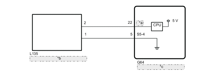
| *a | RRTS |
| *b | Cooler Thermistor (Solar Sensor) |
| *c | Air Conditioning Amplifier Assembly |
PROCEDURE
-
READ VALUE USING GTS (REAR SOLAR SENSOR)
-
Connect the GTS to the DLC3.
-
Turn the engine switch on (IG).
-
Turn the GTS on.
-
Enter the following menus: Body Electrical / Air Conditioner / Data List.
-
Read the Data List according to the display on the GTS.
Body Electrical > Air Conditioner > Data ListTester Display Measurement Item Range Normal Condition Diagnostic Note Rear Solar Sensor Cooler thermistor (solar sensor) 0 to 255 Cooler thermistor (solar sensor) value increases as brightness increases Cooler thermistor (solar sensor) system malfunction
-
When open circuit: 0
-
When short circuit: 255
Body Electrical > Air Conditioner > Data ListTester Display Rear Solar Sensor OK The display is as specified in the normal condition column. Result Proceed to OK NG -
OK 
REPLACE AIR CONDITIONING AMPLIFIER ASSEMBLY Click here
NG 
-
-
INSPECT COOLER THERMISTOR (SOLAR SENSOR)
-
Remove the cooler thermistor (solar sensor).
-
Inspect the cooler thermistor (solar sensor).
Result Proceed to OK NG
NG
REPLACE COOLER THERMISTOR (SOLAR SENSOR) Click here
OK
-
-
CHECK HARNESS AND CONNECTOR (AIR CONDITIONING AMPLIFIER ASSEMBLY - COOLER THERMISTOR (ROOM TEMPERATURE SENSOR))
-
Disconnect the G64 air conditioning amplifier assembly connector.
-
Disconnect the L135 cooler thermistor (solar sensor) connector.
-
Measure the resistance according to the value(s) in the table below.
Standard Resistance Tester Connection Condition Specified Condition G64-22 (RRTS) - L135-2 Always Below 1 Ω G64-5 (S 5-4) - L135-1 Always Below 1 Ω G64-22 (RRTS) or L135-2 - Other terminals and body ground Always 10 kΩ or higher G64-5 (S 5-4) or L135-1 - Other terminals and body ground Always 10 kΩ or higher Result Proceed to OK NG
OK
REPLACE AIR CONDITIONING AMPLIFIER ASSEMBLY Click here
NG
REPAIR OR REPLACE HARNESS OR CONNECTOR
-