ENGINE ON-VEHICLE INSPECTION
PROCEDURE
INSPECT ENGINE COOLANT
INSPECT ENGINE OIL
INSPECT BATTERY
INSPECT AIR CLEANER FILTER ELEMENT SUB-ASSEMBLY
Remove the air cleaner cap sub-assembly.
w/ Glow Plug Controller:
w/o Glow Plug Controller:
Remove the air cleaner filter element sub-assembly.
Visually check that the air cleaner filter element sub-assembly is not excessively damaged or oily. If necessary, replace the air cleaner filter element sub-assembly.
Tip:If there is any foreign matter or clogs in the air cleaner filter element sub-assembly, clean it with compressed air.
If any foreign matter or clogs remain even after cleaning the air cleaner filter element sub-assembly with compressed air, replace it.
Install the air cleaner filter element sub-assembly.
Install the air cleaner cap sub-assembly.
w/ Glow Plug Controller:
w/o Glow Plug Controller:
INSPECT V-RIBBED BELT
INSPECT ENGINE SPEED
Note:Turn all the electrical systems and A/C off.
Inspect the engine idle speed with the cooling fans off.
When checking the idle speed, the transaxle should be in neutral.
Warm up and stop the engine.
When using the GTS:
Connect the GTS to the DLC3.
Turn the ignition switch to ON and turn the tester on.
Start the engine.
Enter the following menus: Powertrain / Engine and ECT / Data List / Engine Speed.
Powertrain > Engine and ECT > Data List
Tester Display
Engine Speed
Tip:Refer to the GTS operator's manual for further information regarding the selection of the Data List.
Inspect the engine idle speed.
Standard Idle Speed
720 to 820 rpm
Fully depress the accelerator pedal.
Inspect the maximum engine speed.
Maximum Speed
5150 to 5250 rpm
Turn the ignition switch off.
Disconnect the GTS from the DLC3.
-
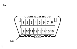
*a
DLC3
When not using the GTS:
Using SST, connect a tachometer probe to terminal 9 (TAC) of the DLC3.
09843-18040
Note:Be sure to connect the tachometer to the correct terminal. Connecting the wrong terminals can cause damage.
Turn the ignition switch to ON.
Start the engine.
Inspect the engine idle speed.
Standard Idle Speed
720 to 820 rpm
Fully depress the accelerator pedal.
Inspect the maximum engine speed.
Maximum Speed
5150 to 5250 rpm
Turn the ignition switch off.
Disconnect the tachometer probe from terminal 9 (TAC) of the DLC3.
INSPECT COMPRESSION (w/ Glow Plug Controller)
Warm up and stop the engine.
Disconnect the negative battery terminal.
-
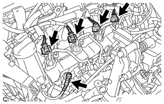
Disconnect the 4 connectors from the 4 injector assemblies.
Remove the 4 glow plug assemblies.
Note:In order to avoid shorting the circuit of the wire harness connected to the glow plug No. 1 connector, wind vinyl tape around the wire harness terminal portion.
Connect the cable to the negative (-) battery terminal.
Crank the engine to remove foreign matter before measuring the compression pressure.
-
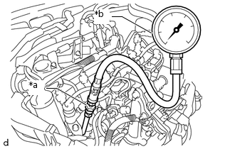
*a
SST (Attachment)
*b
SST (Compression Gauge)
Install SST (attachment) into the glow plug assembly hole.
09992-19015
09992-10070
13 N*m
133 kgf*cm
10 ft.*lbf
Connect SST (compression gauge) to SST (attachment).
09992-19015
09992-10010
09992-10020
While cranking the engine, measure the compression pressure.
Compression Pressure
2300 kPa (23.5 kgf/cm2, 334 psi)
Minimum Pressure
2050 kPa (20.9 kgf/cm2, 297 psi)
Difference between Each Cylinder
500 kPa (5.1 kgf/cm2, 73 psi) or less
Note:Use a fully-charged battery to obtain an engine speed of 250 rpm or more.
Inspect the other cylinders in the same way.
Measure the compression pressure in as short a time as possible.
If the cylinder compression pressure is low, pour a small amount of engine oil into the cylinder through the glow plug assembly hole, and then inspect it again.
Tip:If adding engine oil increases the compression pressure, the piston rings and/or cylinder bore may be worn or damaged.
If the compression pressure stays low, a valve may be stuck or seated improperly, or there may be leaks in the cylinder head gasket.
Remove SST (compression gauge and attachment).
Install the 4 glow plug assemblies.
Connect the 4 connectors to the 4 injector assemblies.
INSPECT COMPRESSION (w/o Glow Plug Controller)
Warm up and stop the engine.
-
Disconnect the 4 connectors from the 4 injector assemblies.
Remove the 4 glow plug assemblies.
Note:In order to avoid shorting the circuit of the wire harness connected to the glow plug No. 1 connector, wind vinyl tape around the wire harness terminal portion.
-
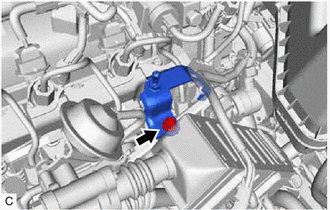
Remove the bolt and separate the No. 3 engine cover bracket.
Connect the cable to the negative (-) battery terminal.
Crank the engine to remove foreign matter before measuring the compression pressure.
-
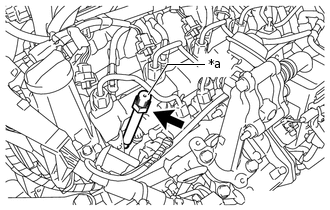
*a
SST (Attachment)
Insert SST (attachment) into the glow plug assembly hole.
09992-19015
09992-10070
13 N*m
133 kgf*cm
10 ft.*lbf
-
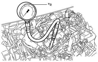
*a
SST (Compression Gauge)
Connect SST (compression gauge) to SST (attachment).
09992-19015
09992-10010
09992-10020
While cranking the engine, measure the compression pressure.
Compression Pressure
2300 kPa (23.5 kgf/cm2, 334 psi)
Minimum Pressure
2050 kPa (20.9 kgf/cm2, 297 psi)
Difference between Each Cylinder
500 kPa (5.1 kgf/cm2, 73 psi) or less
Note:Use a fully-charged battery to obtain an engine speed of 250 rpm or more.
Inspect the other cylinders in the same way.
Measure the compression pressure in as short a time as possible.
If the cylinder compression pressure is low, pour a small amount of engine oil into the cylinder through the glow plug assembly hole, and then inspect it again.
Tip:If adding engine oil increases the compression pressure, the piston rings and/or cylinder bore may be worn or damaged.
If the compression pressure stays low, a valve may be stuck or seated improperly, or there may be leaks in the cylinder head gasket.
Remove SST (compression gauge and attachment).
Install the No. 3 engine cover bracket with the bolt.
9.0 N*m
92 kgf*cm
80 in.*lbf
Install the 4 glow plug assemblies.
Connect the 4 connectors to the 4 injector assemblies.