SEAT ASSEMBLY
-
FUNCTION
-
Front Headrest
-
The headrests have been brought forward compared to vehicles with active headrests and the side frames have been reinforced to control the amount the occupant's body sinks into the seatback, allowing for rapid support of the occupant's head, and achieving excellent safety in the event of a low-speed rear collision.
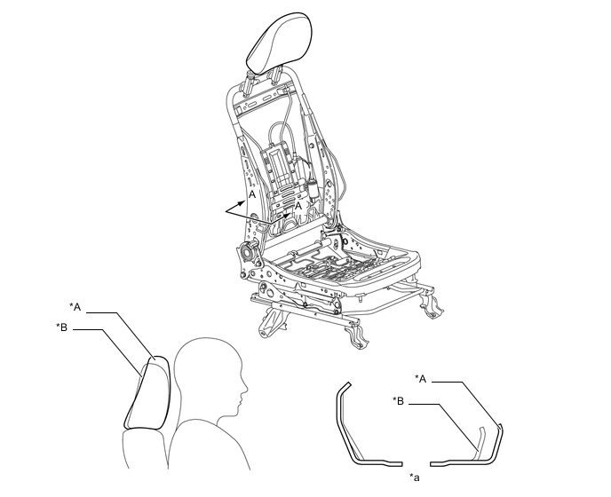
Text in Illustration *A Models with Passive Headrests *B Models with Active Headrests *a A-A Cross Section - -
-
-
Power Lumbar Support
-
The driver seat uses a 2-way adjustable lumbar support. This support includes a plastic basket that is located near the lumbar area of the occupant, and which pushes the seatback forward, thus providing uniform support from the upper back down to the pelvis for a better fit.
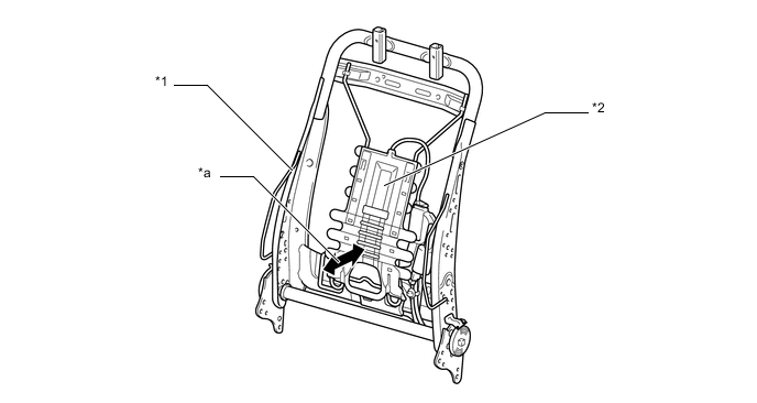
Text in Illustration *1 Seatback Frame *2 Plastic Basket *a Front-back Adjustment - -
-
-
Manual Lifter
-
The driver seat uses a manual lifter. The manual lifter consists of a pump type lifter knob, lifter gear and lifter rod, thus accommodating various body types.
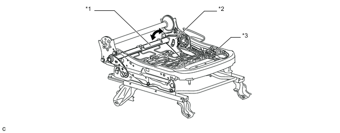
Text in Illustration *1 Lifter Rod *2 Lifter Gear *3 Lifter Knob - -
-
-
-
CONSTRUCTION
-
Child Restraint System
-
ISO-FIX bars for securing child seats have been provided behind the seat cushion of the rear No. 1 seat.
-
CRS top tether anchor brackets for securing a child seat have been provided behind the rear seat backrest.
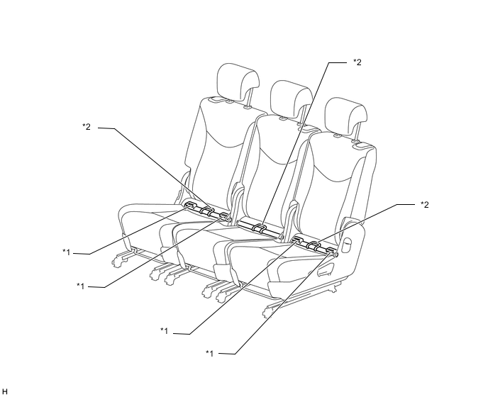
Text in Illustration *1 ISO-FIX Bars *2 CRS Top Tether Anchor Bracket
-
-
Walk-in Mechanism
-
A walk-in mechanism is provided. By operating the reclining control lever and rear seat lock control lever sub-assembly, the seatback can be folded down, and the seat slid forward.
-
The walk-in mechanism mainly consists of a reclining control lever, outer and inner reclining brackets, stopper plates, slide lock links and seat track control cable assembly.
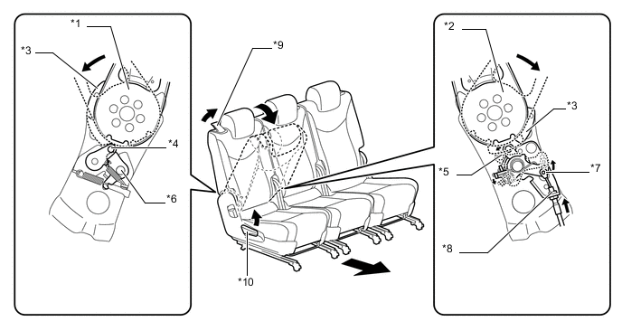
Text in Illustration *1 Outer Reclining Bracket *2 Inner Reclining Bracket *3 Stopper Plate A *4 Pin A *5 Pin B *6 Stopper Plate B *7 Link A *8 Seat Track Control Cable Assembly *9 Reclining Control Lever *10 Rear Seat Lock Control Lever Sub-assembly Walk-in Mechanism Function User Operation Action The reclining control lever and rear seat lock control lever sub-assembly are operated The reclining lock is unlocked. The outer and inner reclining brackets that are secured in the seatback frame can be rotated.
-
Stopper plate A in the outer reclining bracket is secured by stopper plate B via pin A, maintaining the seatback in a walk-in position.
-
Stopper plate A in the inner reclining bracket pushes pin B, rotating the slide lock link to pull up the seat track control cable assembly.
-
The seat track control cable assembly is lifted up, unlocking the slide lock.
The seat slides forward (additional slide stroke: 75mm) Note
Do not operate the walk-in mechanism while the vehicle is being driven.
-
-
-
Seatback Fold Down Mechanism
-
The seatback fold down mechanism is provided. If the No. 1 reclining adjuster release handle is operated when the seatback is in the walk-in position, the seatback is folded to a position that is parallel to the deck floor.
-
The seatback fold down mechanism mainly consists of a No. 1 reclining adjuster release handle, outer and inner reclining brackets, stopper plates, slide lock links and seat track control cable assembly.
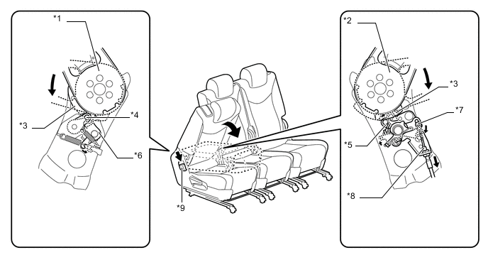
Text in Illustration *1 Outer Reclining Bracket *2 Inner Reclining Bracket *3 Stopper Plate A *4 Pin A *5 Pin B *6 Stopper Plate B *7 Link A *8 Seat Track Control Cable Assembly *9 No. 1 Reclining Adjuster Release Handle - - Seatback Fold Down Mechanism Function User Operation Action The reclining control lever is operated. The seatback is folded to the walk-in position. The No. 1 reclining adjuster release handle is operated. The reclining lock is unlocked. The outer and inner reclining brackets that are secured in the seatback frame can be rotated.
-
Stopper plate B in the outer reclining bracket operates, and pin A is released from stopper plate A, rotating the outer reclining bracket.
-
The stopper plate in the inner reclining bracket locks pin B, and the slide lock link is returned to the original position, pulling up the seat track control cable assembly.
-
The seat track control cable assembly is lifted up, unlocking the slide lock.
Note
Do not operate the walk-in mechanism while the vehicle is being driven.
-
-
-
Tilt Down Mechanism
-
The tilt down mechanism is provided. By operating the seat cushion lock release lever assembly or 3rd seat strap, the seatback can be folded forward to a position that is parallel to the deck floor.
-
Operating the seat cushion lock release lever assembly or 3rd seat strap when the No. 2 headrest assembly is in the retracted position (lowest position) will fold the seatback. In conjunction with the seatback motion, the front of the seat cushion is lowered, allowing the seatback to be retracted.
-
To return the retracted seatback for use, pull up the 3rd seat strap to lift the seatback until the seatback is securely locked.
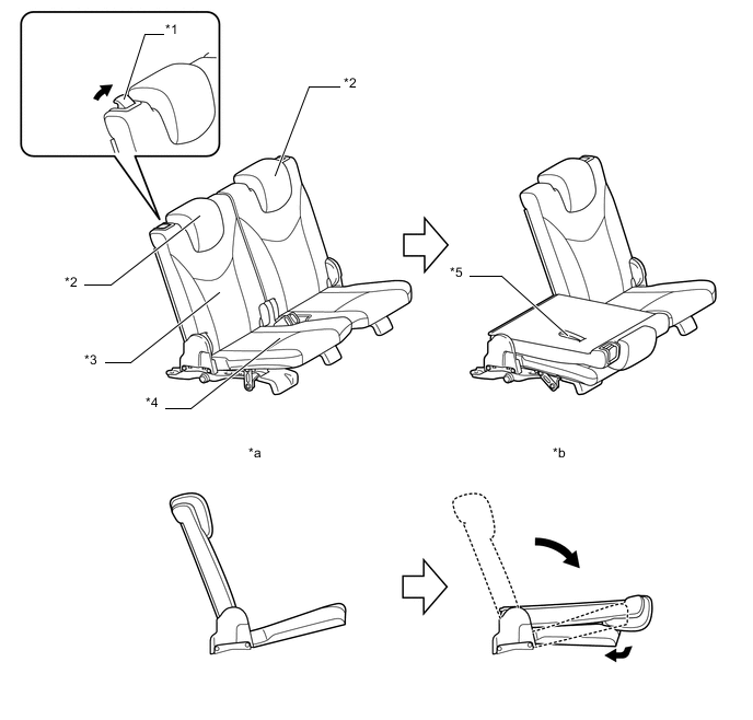
Text in Illustration *1 Seat Cushion Lock Release Lever Assembly *2 No. 2 Headrest Assembly (Lowest Position) *3 Seatback *4 Seat Cushion *5 3rd Seat Strap - - *a Normal State *b Retracted State
-
-