NAVIGATION SYSTEM, Diagnostic DTC:B15C0 and B15C1
| DTC Code | DTC Name |
|---|---|
| B15C0 | GPS Antenna Connection Malfunction(short) |
| B15C1 | GPS Antenna Connection Malfunction(break) |
DESCRIPTION
These DTCs are stored when a malfunction occurs in the navigation antenna assembly.
DTC No. |
Detection Item |
DTC Detection Condition |
Trouble Area |
|---|---|---|---|
B15C0 |
GPS Antenna Connection Malfunction(short) |
Navigation antenna error |
|
B15C1 |
GPS Antenna Connection Malfunction(break) |
Error of the power source to the navigation antenna |
|
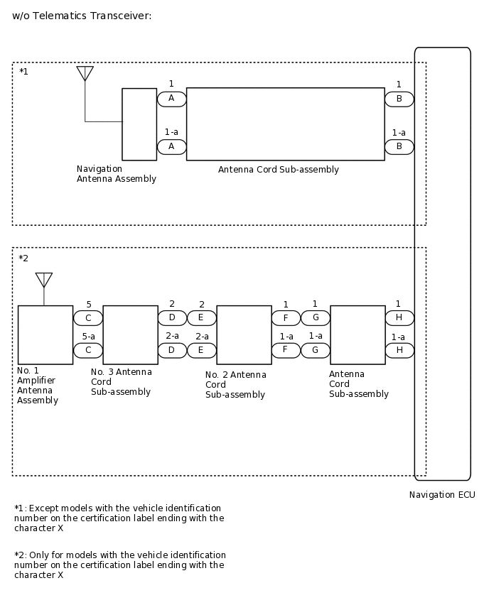
*1: Except models with the vehicle identification number on the certification label ending with the character X.
*2: Only for models with the vehicle identification number on the certification label ending with the character X.
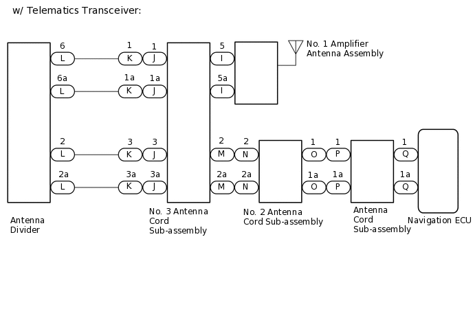
*3: w/ Telematics Transceiver
WIRING DIAGRAM
CAUTION / NOTICE / HINT
Check that the wire harness is properly installed and does not have any sharp bends, pinching or loose connections.
PROCEDURE
CHECK CONNECTION OF NAVIGATION ANTENNA ASSEMBLY
Check if the navigation antenna assembly is securely connected to the antenna cord sub-assembly.
OK
Navigation antenna assembly is securely connected.
Result
Proceed to
OK
NG
NG SECURELY CONNECT NAVIGATION ANTENNA ASSEMBLY
CHECK VEHICLE CONDITION
Check the vehicle condition.
Result
Result
Proceed to
w/o Telematics Transceiver (Except models with the vehicle identification number on the certification label ending with the character X)
A
w/o Telematics Transceiver (Only for models with the vehicle identification number on the certification label ending with the character X)
B
w/ Telematics Transceiver
C
CHECK ANTENNA CORD SUB-ASSEMBLY
-
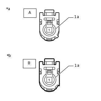
*a
Front view of wire harness connector
(to Navigation Antenna Assembly)
*b
Front view of wire harness connector
(to Navigation ECU)
Disconnect the antenna connector from the navigation ECU.
Disconnect the antenna connector from the navigation antenna assembly.
Measure the resistance according to the value(s) in the table below.
Standard Resistance
Tester Connection
Condition
Specified Condition
A-1 - B-1
Always
Below 1 Ω
A-1a - B-1a
Always
Below 1 Ω
A-1 or B-1 - Body ground
Always
10 kΩ or higher
A-1a or B-1a - Body ground
Always
10 kΩ or higher
Result
Proceed to
OK
NG
-
CHECK NAVIGATION ANTENNA ASSEMBLY
Replace the navigation antenna assembly with a new or known good one.
Clear the DTCs.
Body Electrical > Navigation System > Clear DTCs
Check for DTCs.
Body Electrical > Navigation System > Trouble Codes
OK
No DTCs are output.
Result
Proceed to
OK
NG
OK END (NAVIGATION ANTENNA ASSEMBLY IS DEFECTIVE)
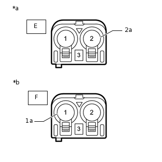
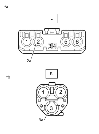
CHECK NO. 3 ANTENNA CORD SUB-ASSEMBLY
-
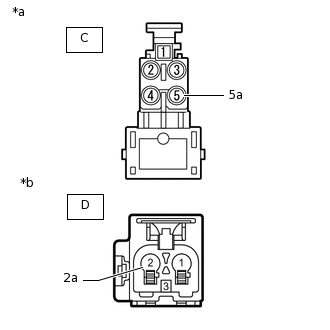
*a
Front view of wire harness connector
(to No. 1 Amplifier Antenna Assembly)
*b
Front view of wire harness connector
(to No. 2 Antenna Cord Sub-assembly)
Disconnect the antenna connector from the No. 1 amplifier antenna assembly.
Disconnect the antenna connector from the No. 2 antenna cord sub-assembly.
Measure the resistance according to the value(s) in the table below.
Standard Resistance
Tester Connection
Condition
Specified Condition
C-5 - D-2
Always
Below 1 Ω
C-5a - D-2a
Always
Below 1 Ω
C-5 or D-2 - Body ground
Always
10 kΩ or higher
C-5a or D-2a - Body ground
Always
10 kΩ or higher
Result
Proceed to
OK
NG
-
CHECK NO. 2 ANTENNA CORD SUB-ASSEMBLY
-
*a
Front view of wire harness connector
(to No. 3 Antenna Cord Sub-assembly)
*b
Front view of wire harness connector
(to Antenna Cord Sub-assembly)
Disconnect the antenna connector from the No. 3 antenna cord sub-assembly.
Disconnect the antenna connector from the antenna cord sub-assembly.
Measure the resistance according to the value(s) in the table below.
Standard Resistance
Tester Connection
Condition
Specified Condition
E-2 - F-1
Always
Below 1 Ω
E-2a - F-1a
Always
Below 1 Ω
E-2 or F-1 - Body ground
Always
10 kΩ or higher
E-2a or F-1a - Body ground
Always
10 kΩ or higher
Result
Proceed to
OK
NG
-
CHECK ANTENNA CORD SUB-ASSEMBLY
-

*a
Front view of wire harness connector
(to No. 2 Antenna Cord Sub-assembly)
*b
Front view of wire harness connector
(to Navigation ECU)
Disconnect the antenna connector from the No. 2 antenna cord sub-assembly.
Disconnect the antenna connector from the navigation ECU.
Measure the resistance according to the value(s) in the table below.
Standard Resistance
Tester Connection
Condition
Specified Condition
G-1 - H-1
Always
Below 1 Ω
G-1a - H-1a
Always
Below 1 Ω
G-1 or H-1 - Body ground
Always
10 kΩ or higher
G-1a or H-1a - Body ground
Always
10 kΩ or higher
Result
Proceed to
OK
NG
-
CHECK NO. 1 AMPLIFIER ANTENNA ASSEMBLY
Replace the No. 1 amplifier antenna assembly with a new or known good one.
Clear the DTCs.
Body Electrical > Navigation System > Clear DTCs
Check for DTCs.
Body Electrical > Navigation System > Trouble Codes
OK
No DTCs are output.
Result
Proceed to
OK
NG
OK END (NO. 1 AMPLIFIER ANTENNA ASSEMBLY IS DEFECTIVE)
CHECK NO. 3 ANTENNA CORD SUB-ASSEMBLY
-
*a
Front view of wire harness connector
(to No. 1 amplifier antenna assembly)
*b
Front view of wire harness connector
(to Wire Harnass)
Disconnect the antenna connector from No. 1 amplifier antenna assembly.
Disconnect the antenna connector from the wire harness.
Measure the resistance according to the value(s) in the table below.
Standard Resistance
Tester Connection
Condition
Specified Condition
I-5 - J-1
Always
Below 1 Ω
I-5a - J-1a
Always
Below 1 Ω
I-5 or J-1 - Body ground
Always
10 kΩ or higher
I-5a or J-1a - Body ground
Always
10 kΩ or higher
Result
Proceed to
OK
NG
-
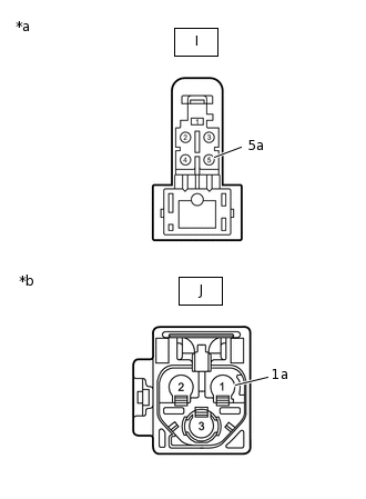
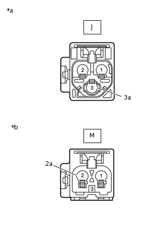
CHECK HARNESS AND CONNECTOR (NO. 3 ANTENNA CORD SUB-ASSEMBLY - ANTENNA DIVIDER)
Disconnect the antenna connector from the No. 3 antenna cord sub-assembly.
Disconnect the antenna connector from the antenna divider.
-
*a
Front view of wire harness connector
(to No. 3 Antenna Cord Sub-assembly)
*a
Front view of wire harness connector
(to Antenna Divider)
Measure the resistance according to the value(s) in the table below.
Standard Resistance
Tester Connection
Condition
Specified Condition
K-1 - L-6
Always
Below 1 Ω
K-1a - L-6a
Always
Below 1 Ω
K-1 or L-6 - Body ground
Always
10 kΩ or higher
K-1a or L-6a - Body ground
Always
10 kΩ or higher
Result
Proceed to
OK
NG
NG REPAIR OR REPLACE HARNESS OR CONNECTOR
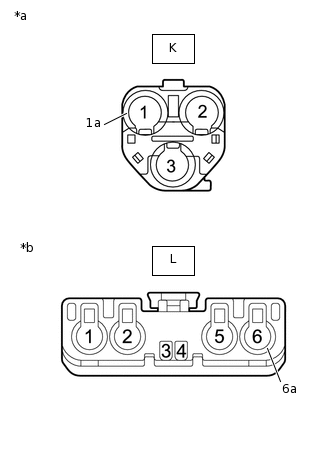
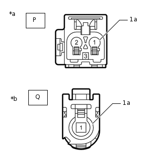
INSPECT ANTENNA DIVIDER
Remove the antenna divider.
-
*a
Component without harness connected
(Antenna Divider)
Measure the resistance according to the value(s) in the table below.
Standard Resistance
Tester Connection
Condition
Specified Condition
6 - 2
Always
10 kΩ or higher
2 - 2a
Always
243 to 267 Ω
6 - 6a
Always
10 kΩ or higher
Result
Proceed to
OK
NG
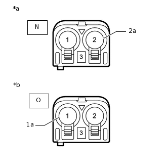
CHECK HARNESS AND CONNECTOR (ANTENNA DIVIDER - NO. 3 ANTENNA CORD SUB-ASSEMBLY)
Disconnect the antenna connector from the No. 3 antenna cord sub-assembly.
Disconnect the antenna connector from the antenna divider.
-
*a
Front view of wire harness connector
(to Antenna Divider)
*a
Front view of wire harness connector
(to No. 3 Antenna Cord Sub-assembly)
Measure the resistance according to the value(s) in the table below.
Standard Resistance
Tester Connection
Condition
Specified Condition
L-2 - K-3
Always
Below 1 Ω
L-2a - K-3a
Always
Below 1 Ω
L-2 or K-3 - Body ground
Always
10 kΩ or higher
L-2a or K-3a - Body ground
Always
10 kΩ or higher
Result
Proceed to
OK
NG
NG REPAIR OR REPLACE HARNESS OR CONNECTOR
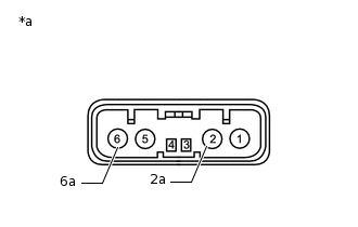
CHECK NO. 3 ANTENNA CORD SUB-ASSEMBLY
-
*a
Front view of wire harness connector
(to wire harness)
*b
Front view of wire harness connector
(to No. 2 Antenna Cord Sub-assembly)
Disconnect the antenna connector from the wire harness.
Disconnect the antenna connector from the No. 2 antenna cord sub-assembly.
Measure the resistance according to the value(s) in the table below.
Standard Resistance
Tester Connection
Condition
Specified Condition
J-3 - M-2
Always
Below 1 Ω
J-3a - M-2a
Always
Below 1 Ω
J-3 or M-2 - Body ground
Always
10 kΩ or higher
J-3a or M-2a - Body ground
Always
10 kΩ or higher
Result
Proceed to
OK
NG
-
CHECK NO. 2 ANTENNA CORD SUB-ASSEMBLY
-
*a
Front view of wire harness connector
(to No. 3 Antenna Cord Sub-assembly)
*b
Front view of wire harness connector
(to Antenna Cord Sub-assembly)
Disconnect the antenna connector from the No. 3 antenna cord sub-assembly.
Disconnect the antenna connector from the antenna cord sub-assembly.
Measure the resistance according to the value(s) in the table below.
Standard Resistance
Tester Connection
Condition
Specified Condition
N-2 - O-1
Always
Below 1 Ω
N-2a - O-1a
Always
Below 1 Ω
N-2 or O-1 - Body ground
Always
10 kΩ or higher
N-2a or O-1a - Body ground
Always
10 kΩ or higher
Result
Proceed to
OK
NG
-
CHECK ANTENNA CORD SUB-ASSEMBLY
-
*a
Front view of wire harness connector
(to No. 2 Antenna Cord Sub-assembly)
*b
Front view of wire harness connector
(to Navigation ECU)
Disconnect the antenna connector from the No. 2 antenna cord sub-assembly.
Disconnect the antenna connector from the navigation ECU.
Measure the resistance according to the value(s) in the table below.
Standard Resistance
Tester Connection
Condition
Specified Condition
P-1 - Q-1
Always
Below 1 Ω
P-1a - Q-1a
Always
Below 1 Ω
P-1 or Q-1 - Body ground
Always
10 kΩ or higher
P-1a or Q-1a - Body ground
Always
10 kΩ or higher
Result
Proceed to
OK
NG
-
CHECK NO. 1 AMPLIFIER ANTENNA ASSEMBLY
Replace the No. 1 amplifier antenna assembly with a new or known good one.
Clear the DTCs.
Body Electrical > Navigation System > Clear DTCs
Check for DTCs.
Body Electrical > Navigation System > Trouble Codes
OK
No DTCs are output.
Result
Proceed to
OK
NG
OK END (NO. 1 AMPLIFIER ANTENNA ASSEMBLY IS DEFECTIVE)
CHECK ANTENNA DIVIDER
Replace the antenna divider with a new or known good one.
Clear the DTCs.
Body Electrical > Navigation System > Clear DTCs
Check for DTCs.
Body Electrical > Navigation System > Trouble Codes
OK
No DTCs are output.
Result
Proceed to
OK
NG
OK END (ANTENNA DIVIDER IS DEFECTIVE)