CAMSHAFT REMOVAL
PROCEDURE
PRECAUTION
Note:After turning the ignition switch off, waiting time may be required before disconnecting the cable from the battery terminal. Therefore, make sure to read the disconnecting the cable from the battery terminal notice before proceeding with work.
DISCONNECT CABLE FROM NEGATIVE BATTERY TERMINAL
Note:When disconnecting the cable, some systems need to be initialized after the cable is reconnected.
Click hereClick hereClick hereClick hereClick hereClick here
REMOVE REAR ENGINE UNDER COVER RH
REMOVE NO. 1 ENGINE COVER SUB-ASSEMBLY
REMOVE AIR CLEANER CAP SUB-ASSEMBLY
REMOVE AIR CLEANER CASE
DISCONNECT RADIATOR RESERVOIR ASSEMBLY
DISCONNECT ENGINE WIRE
-
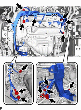
Disconnect the connectors and clamps, remove the bolts and nuts and disconnect the engine wire from the engine.
-
REMOVE IGNITION COIL ASSEMBLY
REMOVE CRANKSHAFT POSITION SENSOR
REMOVE CYLINDER HEAD COVER SUB-ASSEMBLY
SET NO. 1 CYLINDER TO TDC/COMPRESSION
-
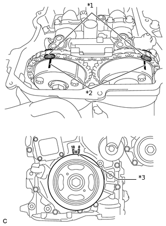
*1
Paint Mark
*2
Matchmark
*3
Timing Notch (Groove)
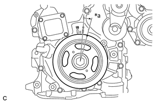
Turn the crankshaft pulley until its timing notch (groove) and the timing mark "0" of the timing chain cover are aligned.
Check that each matchmark of the camshaft timing gear and camshaft timing exhaust gear are aligned with each matchmark located as shown in the illustration. If not, turn the crankshaft 1 revolution (360°) to align the timing marks as shown in the illustration.
Place paint marks on the chain in alignment with the timing marks on the camshaft timing gear and camshaft timing exhaust gear.
-
REMOVE TIMING CHAIN COVER PLATE
-
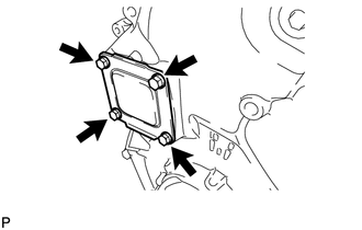
Remove the 4 bolts, timing chain cover plate and gasket.
-
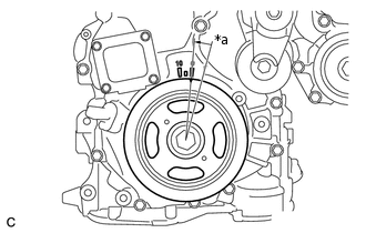
REMOVE NO. 1 CHAIN TENSIONER ASSEMBLY
-

*a
Approximately 10°
Turn the crankshaft approximately 10° clockwise.
-
*a
Approximately 10°
Turn the crankshaft approximately 10° counterclockwise.
-
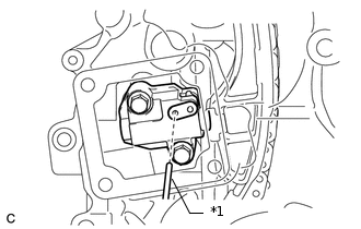
*1
Pin
Align the holes of the stopper plate and tensioner, and insert a pin into the stopper plate hole to lock the tensioner.
-
*a
Approximately 10°
Turn the crankshaft approximately 10° clockwise.
-
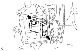
Remove the 2 bolts, No. 1 chain tensioner and gasket.
Note:Make sure not to drop the gasket inside the timing chain cover.
-

*a
Approximately 10°
Turn the crankshaft approximately 10° counterclockwise.
-
REMOVE TIMING CHAIN GUIDE
REMOVE TIMING CHAIN COVER TIGHT PLUG
REMOVE CAMSHAFT TIMING GEAR ASSEMBLY
-
Hold the hexagonal portion of the camshaft with a wrench and remove the bolt from the camshaft.
Note:Be careful not to damage the cylinder head or spark plug tube with the wrench.
-
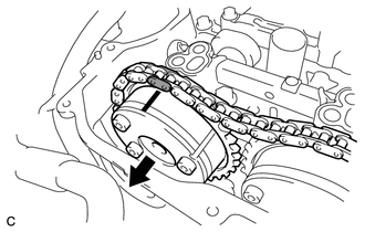
Separate the camshaft timing gear assembly from the camshaft.
-
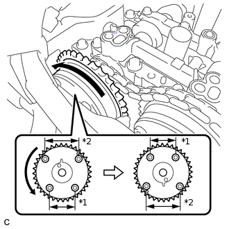
*1
Narrow
*2
Wide
Remove the timing chain from the camshaft timing gear assembly, and turn the camshaft timing gear assembly approximately 180°.
-
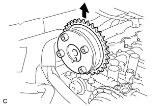
Remove the camshaft timing gear assembly.
Note:Do not disassemble the camshaft timing gear.
-
REMOVE CAMSHAFT BEARING CAP
-
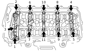
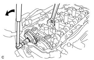
Using several steps, remove the 11 bearing cap bolts in the sequence shown in the illustration.
-
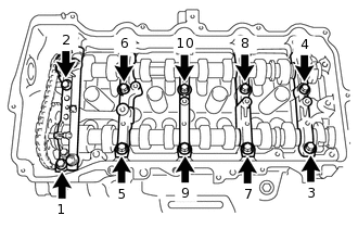
Using several steps, remove the 10 bearing cap bolts in the sequence shown in the illustration.
Remove the 5 camshaft bearing caps.
Tip:Arrange the removed parts in the correct order.
-
REMOVE CAMSHAFT
-
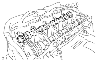
Remove the camshaft from the camshaft housing.
-
REMOVE NO. 2 CAMSHAFT
-
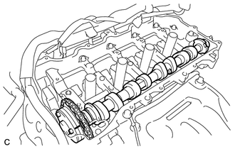
Hold up the chain and remove the No. 2 camshaft from the camshaft housing.
-
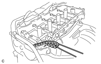
Suspend the chain with a string or equivalent as shown in the illustration.
Note:Be careful not to drop the chain inside the timing chain cover.
-
REMOVE CAMSHAFT TIMING EXHAUST GEAR ASSEMBLY
-
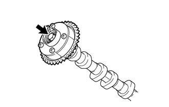
Remove the flange bolt and camshaft timing exhaust gear assembly.
Note:Do not disassemble the camshaft timing exhaust gear.
-
REMOVE OIL CONTROL VALVE FILTER
REMOVE NO. 1 CAMSHAFT BEARING
REMOVE NO. 2 CAMSHAFT BEARING