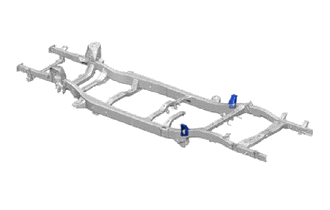
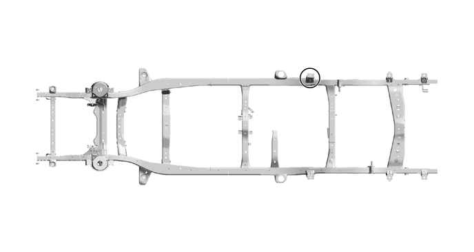
DECK MOUNTING NO.1 BRACKET(for Smart Cab) ASSEMBLY REPLACEMENT
Tech Tips
-
Use the same procedure for the RH and LH.
-
The procedure listed below is for the RH.
-
REMOVAL
Symbol Meaning 
Cut with Disc Sander etc. 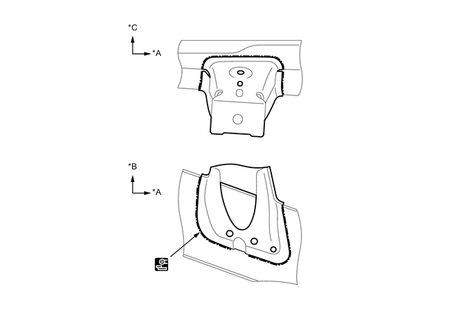
*A FRONT *B UPPER *C LH - - -
INSTALLATION
Symbol Meaning 
Fillet Weld
-
Temporarily install the new parts and measure each part of the new parts in accordance with the body dimension diagram. (See the body dimensions)
-
Make sure that proper welding can be performed by setting up the welding conditions as necessary before performing work.
-
Before installing the upper body, confirm the alignment of the upper body and frame.
-
To prevent heat deformation, weld the right and left side of each part before continuing to the next part.
-
Make sure that the welding bead at A is overlapped.
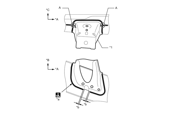
*A FRONT *B UPPER *C LH - - *1 REAR BODY MOUNTING BRACKET SUB-ASSEMBLY NO.2 - - *a 496 mm (19.53 in.) *b 5 +/- 5 mm (0.20 +/- 0.20 in.) -
After applying the top coat, apply anti-rust agent to the internal panel portion of the closed section structural weld points.
-