THEFT DETERRENT SYSTEM Rear Door Courtesy Switch RH Circuit
DESCRIPTION
The theft warning ECU assembly detects the condition of the rear door courtesy light switch assembly RH.
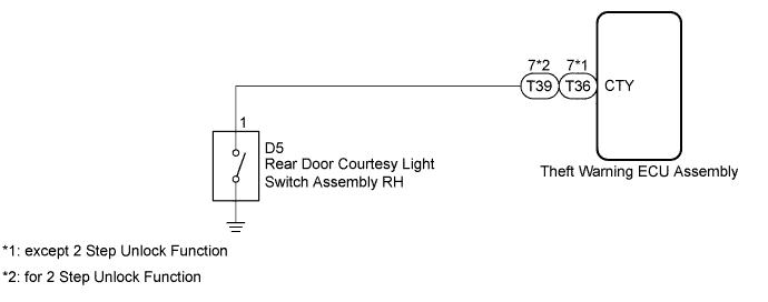
WIRING DIAGRAM
INSPECTION PROCEDURE
PROCEDURE
-
INSPECT REAR DOOR COURTESY LIGHT SWITCH ASSEMBLY RH
-
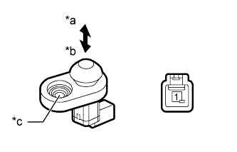
Text in Illustration *a Not pushed (ON) *b Pushed (OFF) *c Body ground Remove the rear door courtesy light switch assembly Click here.
-
Measure the resistance according to the value(s) in the table below.
Standard Resistance Tester Connection Switch Condition Specified Condition 1 - Body ground Not pushed (ON) Below 1 Ω 1 - Body ground Pushed (OFF) 10 kΩ or higher
NG 
REPLACE REAR DOOR COURTESY LIGHT SWITCH ASSEMBLY RH Click here
OK 
-
-
CHECK HARNESS AND CONNECTOR (REAR DOOR COURTESY LIGHT SWITCH RH - THEFT WARNING ECU)
-
Disconnect the D5 rear door courtesy light switch assembly RH connector.
-
Disconnect the T36*1 or T39*2 theft warning ECU assembly connector.
-
*1: except 2 Step Unlock Function
-
*2: for 2 Step Unlock Function
-
-
Measure the resistance according to the value(s) in the table below.
Standard Resistance except 2 Step Unlock Function Tester Connection Condition Specified Condition D5-1 - T36-7 (CTY) Always Below 1 Ω D5-1 or T36-7 (CTY) - Body ground Always 10 kΩ or higher for 2 Step Unlock Function Tester Connection Condition Specified Condition D5-1 - T39-7 (CTY) Always Below 1 Ω D5-1 or T39-7 (CTY) - Body ground Always 10 kΩ or higher
NG
REPAIR OR REPLACE HARNESS OR CONNECTOR
OK 
PROCEED TO NEXT CIRCUIT INSPECTION SHOWN IN PROBLEM SYMPTOMS TABLE Click here
-