AUDIO AND VISUAL SYSTEM(w/ Navigation System) Microphone Circuit between Microphone and Navigation Receiver Assembly
| DTC Code | DTC Name |
|---|---|
| Microphone Circuit between Microphone and Navigation Receiver Assembly |
DESCRIPTION
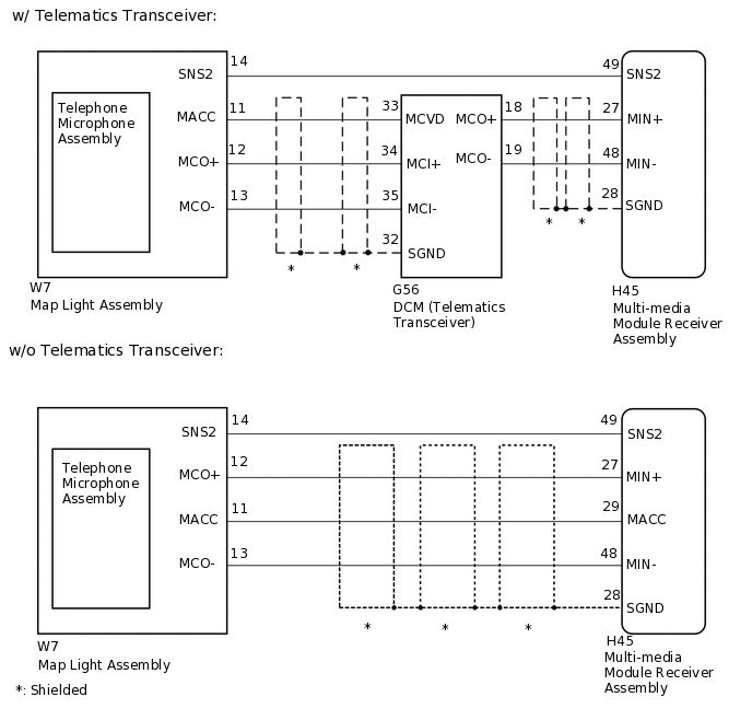
The multi-media module receiver assembly and map light assembly (telephone microphone assembly) are connected to each other using the microphone connection detection signal lines.
Using this circuit, the multi-media module receiver assembly sends power to the map light assembly (telephone microphone assembly), and the map light assembly (telephone microphone assembly) sends microphone signals to the multi-media module receiver assembly (w/o Telematics Transceiver).
Using this circuit, the DCM (telematics transceiver) sends power to the map light assembly (telephone microphone assembly), and the map light assembly (telephone microphone assembly) sends microphone signals to the multi-media module receiver assembly via the DCM (telematics transceiver) (w/ Telematics Transceiver).
WIRING DIAGRAM
CAUTION / NOTICE / HINT
If the DCM (telematics transceiver) has been replaced, perform the DCM Activation procedure using the GTS (w/ Telematics Transceiver).
PROCEDURE
CONFIRM MODEL
Choose the model to be inspected.
Model
Model
Proceed to
w/o Telematics Transceiver
A
w/ Telematics Transceiver
B
B CHECK HARNESS AND CONNECTOR (MULTI-MEDIA MODULE RECEIVER ASSEMBLY - MAP LIGHT ASSEMBLY)Click here
CHECK HARNESS AND CONNECTOR (MULTI-MEDIA MODULE RECEIVER ASSEMBLY - MAP LIGHT ASSEMBLY)
Disconnect the H45 multi-media module receiver assembly connector.
Disconnect the W7 map light assembly connector.
Measure the resistance according to the value(s) in the table below.
Standard Resistance
Tester Connection
Condition
Specified Condition
H45-27 (MIN+) - W7-12 (MCO+)
Always
Below 1 Ω
H45-29 (MACC) - W7-11 (MACC)
Always
Below 1 Ω
H45-48 (MIN-) - W7-13 (MCO-)
Always
Below 1 Ω
H45-49 (SNS2) - W7-14 (SNS2)
Always
Below 1 Ω
H45-27 (MIN+) - Body ground
Always
10 kΩ or higher
H45-28 (SGND) - Body ground
Always
10 kΩ or higher
H45-29 (MACC) - Body ground
Always
10 kΩ or higher
H45-48 (MIN-) - Body ground
Always
10 kΩ or higher
H45-49 (SNS2) - Body ground
Always
10 kΩ or higher
Result
Proceed to
OK
NG
NG REPAIR OR REPLACE HARNESS OR CONNECTOR
CHECK MULTI-MEDIA MODULE RECEIVER ASSEMBLY
-
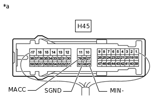
*a
Component with harness connected
(Multi-media Module Receiver Assembly)
Measure the voltage according to the value(s) in the table below.
Standard Voltage
Tester Connection
Switch Condition
Specified Condition
H45-29 (MACC) - Body ground
Engine switch on (ACC)
4 to 6 V
Measure the resistance according to the value(s) in the table below.
Standard Resistance
Tester Connection
Condition
Specified Condition
H45-28 (SGND) - Body ground
Always
Below 1 Ω
H45-48 (MIN-) - Body ground
Always
Below 1 Ω
Result
Proceed to
OK
NG
-
CHECK MULTI-MEDIA MODULE RECEIVER ASSEMBLY
-
*a
Component with harness connected
(Multi-media Module Receiver Assembly)
Measure the voltage according to the value(s) in the table below.
Standard Voltage
Tester Connection
Switch Condition
Specified Condition
H45-29 (MACC) - Body ground
Engine switch on (ACC)
4 to 6 V
Measure the resistance according to the value(s) in the table below.
Standard Resistance
Tester Connection
Condition
Specified Condition
H45-28 (SGND) - Body ground
Always
Below 1 Ω
H45-48 (MIN-) - Body ground
Always
Below 1 Ω
Result
Proceed to
OK
NG
NG CHECK TELEPHONE MICROPHONE ASSEMBLYClick here
-
CHECK MAP LIGHT ASSEMBLY
Turn the engine switch on (ACC).
Connect an oscilloscope to terminals W7-12 (MCO+) and W7-13 (MCO-) of the map light assembly connector.
-
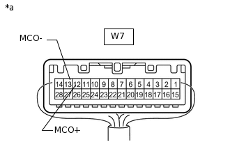
*a
Component with harness connected
(Map Light Assembly)
Check the waveform of the telephone microphone assembly using the oscilloscope.
Proceed to the next step based on the inspection result.
Result
Result
Proceed to
A waveform synchronized with the voice input to the map light assembly is output.
A
A waveform synchronized with the voice input to the map light assembly is not output.
B
CHECK TELEPHONE MICROPHONE ASSEMBLY
Replace the telephone microphone assembly with a known good one.
Check if the same DTC is output again.
OK
No DTCs are output.
Result
Proceed to
OK
NG
OK END (TELEPHONE MICROPHONE ASSEMBLY IS DEFECTIVE)
CHECK HARNESS AND CONNECTOR (MULTI-MEDIA MODULE RECEIVER ASSEMBLY - MAP LIGHT ASSEMBLY)
Disconnect the H45 multi-media module receiver assembly connector.
Disconnect the W7 map light assembly connector.
Measure the resistance according to the value(s) in the table below.
Standard Resistance
Tester Connection
Condition
Specified Condition
H45-49 (SNS2) - W7-14 (SNS2)
Always
Below 1 Ω
Result
Proceed to
OK
NG
NG REPAIR OR REPLACE HARNESS OR CONNECTOR
CHECK HARNESS AND CONNECTOR (MULTI-MEDIA MODULE RECEIVER ASSEMBLY - DCM [TELEMATICS TRANSCEIVER])
Disconnect the H45 multi-media module receiver assembly connector.
Disconnect the G56 DCM (telematics transceiver) connector.
Measure the resistance according to the value(s) in the table below.
Standard Resistance
Tester Connection
Condition
Specified Condition
H45-27 (MIN+) - G56-18 (MCO+)
Always
Below 1 Ω
H45-48 (MIN-) - G56-19 (MCO-)
Always
Below 1 Ω
H45-27 (MIN+) - Body ground
Always
10 kΩ or higher
H45-48 (MIN-) - Body ground
Always
10 kΩ or higher
H45-28 (SGND) - Body ground
Always
10 kΩ or higher
Result
Proceed to
OK
NG
NG REPAIR OR REPLACE HARNESS OR CONNECTOR
CHECK HARNESS AND CONNECTOR (DCM [TELEMATICS TRANSCEIVER] - MAP LIGHT ASSEMBLY)
Disconnect the G56 DCM (telematics transceiver) connector.
Click here
Disconnect the W7 map light assembly connector.
Measure the resistance according to the value(s) in the table below.
Standard Resistance
Tester Connection
Condition
Specified Condition
G56-33 (MCVD) - W7-11 (MACC)
Always
Below 1 Ω
G56-34 (MCI+) - W7-12 (MCO+)
Always
Below 1 Ω
G56-35 (MCI-) - W7-13 (MCO-)
Always
Below 1 Ω
G56-33 (MCVD) - Body ground
Always
10 kΩ or higher
G56-34 (MCI+) - Body ground
Always
10 kΩ or higher
G56-35 (MCI-) - Body ground
Always
10 kΩ or higher
G56-32 (SGND) - Body ground
Always
10 kΩ or higher
Result
Proceed to
OK
NG
NG REPAIR OR REPLACE HARNESS OR CONNECTOR
CHECK MULTI-MEDIA MODULE RECEIVER ASSEMBLY
-
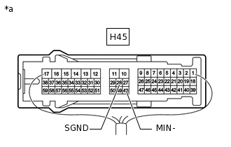
*a
Component with harness connected
(Multi-media Module Receiver Assembly)
Disconnect the G56 DCM (telematics transceiver) connector.
Measure the resistance according to the value(s) in the table below.
Standard Resistance
Tester Connection
Condition
Specified Condition
H45-28 (SGND) - Body ground
Always
Below 1 Ω
H45-48 (MIN-) - Body ground
Always
Below 1 Ω
Result
Proceed to
OK
NG
-
CHECK DCM (TELEMATICS TRANSCEIVER)
-
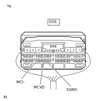
*a
Component with harness connected
(DCM [Telematics Transceiver])
Measure the voltage according to the value(s) in the table below.
Standard Voltage
Tester Connection
Switch Condition
Specified Condition
G56-33 (MCVD) - Body ground
Engine switch on (ACC)
4 to 6 V
Measure the resistance according to the value(s) in the table below.
Standard Resistance
Tester Connection
Condition
Specified Condition
G56-32 (SGND) - Body ground
Always
Below 1 Ω
G56-35 (MCI-) - Body ground
Always
Below 1 Ω
Result
Proceed to
OK
NG
-
INSPECT MAP LIGHT ASSEMBLY
-
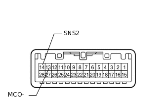
Remove the map light assembly.
Measure the resistance according to the value(s) in the table below.
Standard Resistance
Tester Connection
Condition
Specified Condition
13 (MCO-) - 14 (SNS2)
Always
Below 1 Ω
Result
Proceed to
OK
NG
NG CHECK TELEPHONE MICROPHONE ASSEMBLYClick here
-
CHECK MAP LIGHT ASSEMBLY
-
*a
Component with harness connected
(Map Light Assembly)
Turn the engine switch on (ACC).
Connect an oscilloscope to terminals W7-12 (MCO+) and W7-13 (MCO-) of the map light assembly connector.
Check the waveform of the telephone microphone assembly using the oscilloscope.
Result
Result
Proceed to
A waveform synchronized with the voice input to the map light assembly is output.
A
A waveform synchronized with the voice input to the map light assembly is not output.
B
-
CHECK TELEPHONE MICROPHONE ASSEMBLY
Replace the telephone microphone assembly with a new or normally functioning one.
Check if the same DTC is output again.
Body Electrical > Navigation System > Trouble Codes
OK
No DTCs are output.
Result
Proceed to
OK
NG
OK END (TELEPHONE MICROPHONE ASSEMBLY IS DEFECTIVE)