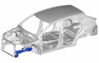
FRONT SIDE MEMBER ASSEMBLY REPLACEMENT
-
With the front fender apron assembly removed.
-
REMOVAL
Symbol Meaning 
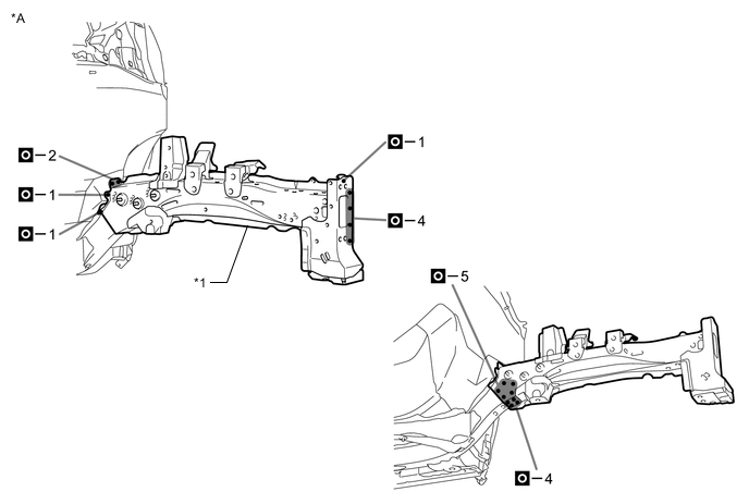
Remove Weld Points 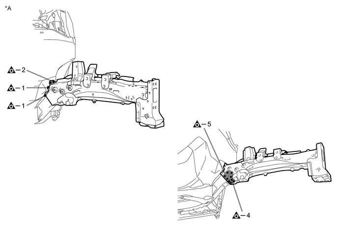
*A LH - - 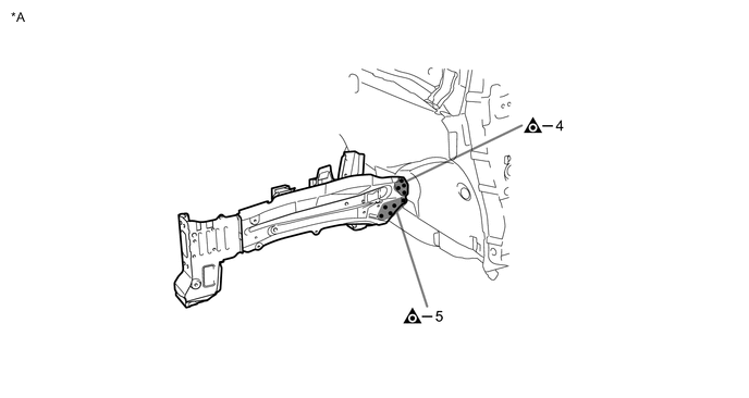
*A LH - - 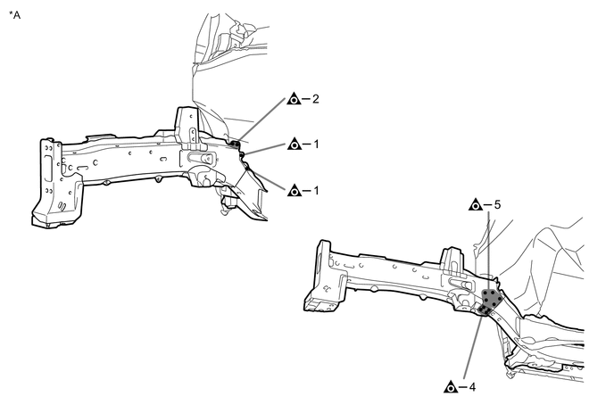
*A RH - - 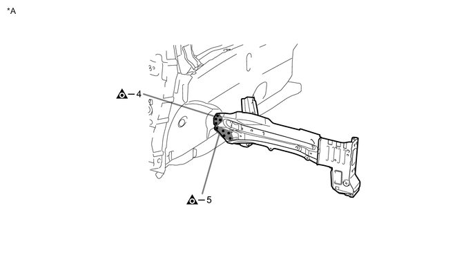
*A RH - - -
INSTALLATION
Symbol Meaning 
Plug Weld 
Fillet Weld
-
Temporarily install the new parts and measure each part of the new parts in accordance with the body dimension diagram. (See the body dimensions)
-
Make sure to attach correctly in accordance with the body dimension diagram as this part affects the front wheel alignment.
-
Weld the front side member inner to the vehicle side.
*A LH - - *1 FRONT SIDE MEMBER INNER - - -
Weld the front side member sub-assembly outer to the vehicle side.
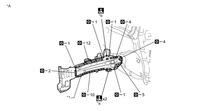
*A LH - - *1 FRONT SIDE MEMBER SUB-ASSEMBLY OUTER - - *a 45 mm (1.77 in.) *b 16 mm (0.63 in.) -
Weld the front side member inner to the vehicle side.
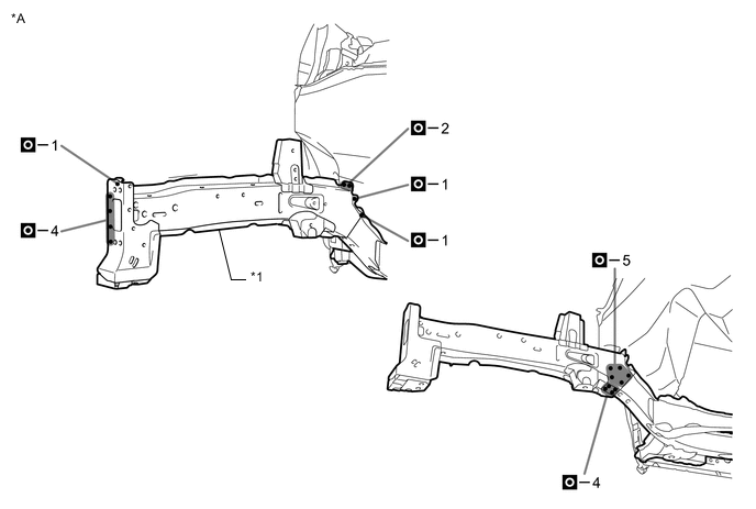
*A RH - - *1 FRONT SIDE MEMBER INNER - - -
Weld the front side member sub-assembly outer to the vehicle side.
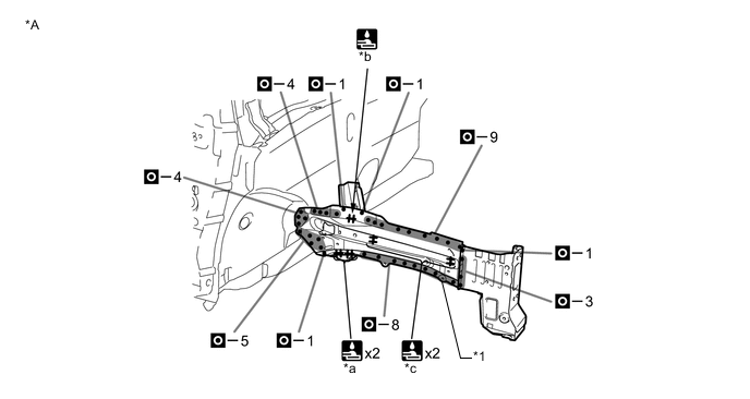
*A RH - - *1 FRONT SIDE MEMBER SUB-ASSEMBLY OUTER - - *a 45 mm (1.77 in.) *b 16 mm (0.63 in.) *c 13 mm (0.51 in.) - - -
After welding, apply body sealer and undercoating to the corresponding parts. (See the painting /coating)
-
After applying the top coat, apply anti-rust agent to the internal panel portion of the closed section structural weld points.
-