SFI SYSTEM(for Rear Air Fuel Ratio Sensor), Diagnostic DTC:P007A11
| DTC Code | DTC Name |
|---|---|
| P007A11 | Charge Air Cooler Temperature Sensor Bank 1 Circuit Short to Ground |
DESCRIPTION
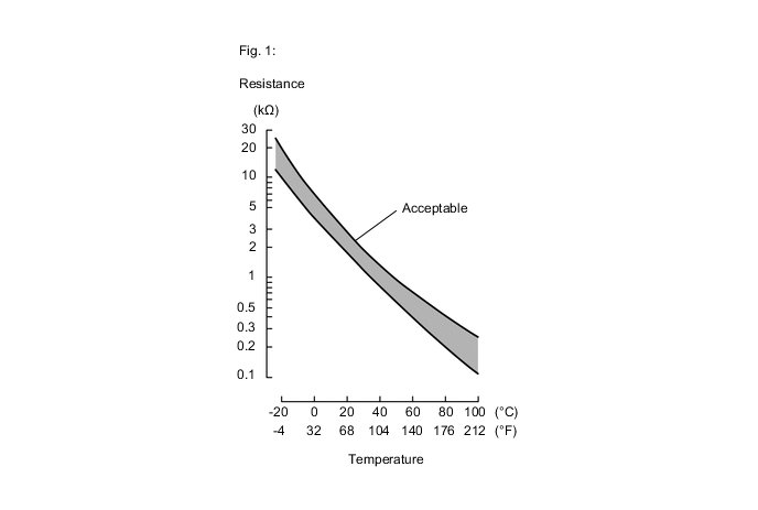
The intake air temperature sensor, built into the No. 1 turbo pressure sensor, monitors the intake air temperature. The intake air temperature sensor has a built-in thermistor with a resistance that varies according to the temperature of the intake air. When the intake air temperature is low, the resistance of the thermistor increases. When the temperature is high, the resistance drops. These variations in resistance are transmitted to the ECM as voltage changes (See Fig. 1).
The intake air temperature sensor is powered by a 5 V supply from terminal THIM of the ECM, via resistor R.
Resistor R and the intake air temperature sensor are connected in series. When the resistance value of the intake air temperature sensor changes, according to changes in the intake air temperature, the voltage at terminal THIM also varies. Based on this signal, the ECM increases the fuel injection volume when the engine is cold to improve driveability.
Tech Tips
When DTC P007A11 is stored, the ECM enters fail-safe mode. During fail-safe mode, the intake air temperature is estimated to be 45°C (113°F) by the ECM. Fail-safe mode continues until a pass condition is detected.
| DTC No. | Detection Item | DTC Detection Condition | Trouble Area | MIL | Memory | Note |
|---|---|---|---|---|---|---|
| P007A11 | Charge Air Cooler Temperature Sensor Bank 1 Circuit Short to Ground | The intake air temperature sensor output voltage is less than 0.1 V for 3 seconds or more (1 trip detection logic). |
|
Comes on (w/ Canister Pump Module) / Does not come on (w/o Canister Pump Module) | DTC stored | SAE Code: P007C |
Tech Tips
When this DTC is output, check the Intake Air Temperature B1S1 (Turbo) in the Data List. Enter the following menus: Powertrain / Engine / Data List / Intake Air Temperature B1S1 (Turbo).
| DTC No. | Intake Air Temperature B1S1 (Turbo) | Malfunction |
|---|---|---|
| P007A11 | 140°C (284°F) | Short in THIM circuit to ground |
If the Data List values is normal it may be due to a temporary recovery from the malfunction condition. Check for intermittent problems.
MONITOR DESCRIPTION
The ECM monitors the sensor voltage and uses this value to calculate the intake air temperature. When the intake air temperature sensor output voltage deviates from the normal operating range, the ECM interprets this as a malfunction in the intake air temperature sensor circuit and stores this DTC.
Example:
If the intake air temperature sensor output voltage is less than 0.1 V for 3 seconds or more, the ECM stores this DTC.
CONFIRMATION DRIVING PATTERN
-
Connect the GTS to the DLC3.
-
Turn the engine switch on (IG).
-
Turn the GTS on.
-
Clear the DTCs (even if no DTCs are stored, perform the clear DTC procedure).
-
Turn the engine switch off and wait for at least 30 seconds.
-
Turn the engine switch on (IG).
-
Turn the GTS on.
-
Wait 5 seconds or more.
-
Enter the following menus: Powertrain / Engine / Trouble Codes.
-
Read the pending DTCs.
Tech Tips
-
If a pending DTC is output, the system is malfunctioning.
-
If a pending DTC is not output, perform the following procedure.
-
-
Enter the following menus: Powertrain / Engine / Utility / All Readiness.
-
Input the DTC: P007A11.
-
Check the DTC judgment result.
GTS Display Description NORMAL
-
DTC judgment completed
-
System normal
ABNORMAL
-
DTC judgment completed
-
System abnormal
INCOMPLETE
-
DTC judgment not completed
-
Perform driving pattern after confirming DTC enabling conditions
Tech Tips
-
If the judgment result shows NORMAL, the system is normal.
-
If the judgment result shows ABNORMAL, the system has a malfunction.
-
If the judgment result shows INCOMPLETE, perform the Confirmation Driving Pattern and check the DTC judgment result again.
-
WIRING DIAGRAM
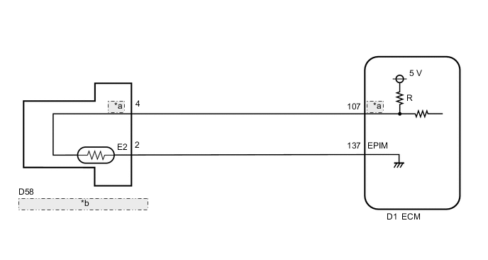
| *a | THIM |
| *b | Intake Air Temperature Sensor (No. 1 Turbo Pressure Sensor) |
CAUTION / NOTICE / HINT
Tech Tips
Read Freeze Frame Data using the GTS. The ECM records vehicle and driving condition information as Freeze Frame Data the moment a DTC is stored. When troubleshooting, Freeze Frame Data can help determine if the vehicle was moving or stationary, if the engine was warmed up or not, if the air fuel ratio was lean or rich, and other data from the time the malfunction occurred.
PROCEDURE
-
READ VALUE USING GTS (CHECK FOR SHORT IN WIRE HARNESS)
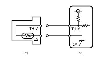
*1 No. 1 turbo pressure sensor *2 ECM
-
Disconnect the No. 1 turbo pressure sensor connector.
-
Connect the GTS to the DLC3.
-
Turn the engine switch on (IG).
-
Turn the GTS on.
-
Enter the following menus: Powertrain / Engine / Data List / Intake Air Temperature B1S1 (Turbo).
Powertrain > Engine > Data ListTester Display Intake Air Temperature B1S1 (Turbo) -
According to the display on the GTS, read the Data List.
OK GTS Display Specified Condition Intake Air Temperature B1S1 (Turbo) -40°C (-40°F) Result Proceed to OK NG
OK 
REPLACE NO. 1 TURBO PRESSURE SENSOR Click here
NG 
-
-
CHECK HARNESS AND CONNECTOR (NO. 1 TURBO PRESSURE SENSOR - ECM)
-
Disconnect the No. 1 turbo pressure sensor connector.
-
Disconnect the ECM connector.
-
Measure the resistance according to the value(s) in the table below.
Standard Resistance Tester Connection Condition Specified Condition D58-4 (THIM) or D1-107 (THIM) - Body ground and other terminals Always 10 kΩ or higher Result Proceed to OK NG
OK
REPLACE ECM Click here
NG
REPAIR OR REPLACE HARNESS OR CONNECTOR
-