SHIFT LEVER ASSEMBLY INSTALLATION
PROCEDURE
INSTALL SHIFT LEVER ASSEMBLY
-
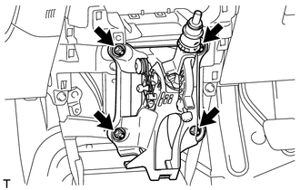
Install the shift lever assembly with the 4 nuts.
12 N*m
122 kgf*cm
9 ft.*lbf
-
INSTALL TRANSMISSION CONTROL CABLE ASSEMBLY
-
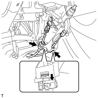
Attach the 2 claws and connect the control cable assembly to the shift lever assembly.
Note:Make sure that the claws are firmly engaged.
-
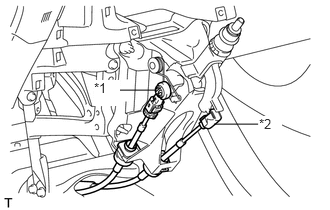
Connect the control shift cable to the shift lever assembly.
Table 1. Text in Illustration *1
Select Cable
*2
Shift Cable
Connect the control select cable to the shift lever assembly.
-
ADJUST CONTROL SELECT CABLE
Adjust the control select cable (Click hereClick here).
INSTALL LOWER NO. 1 INSTRUMENT PANEL FINISH PANEL
INSTALL FRONT NO. 2 CONSOLE BOX INSERT
INSTALL FRONT NO. 1 CONSOLE BOX INSERT
INSTALL LOWER CENTER INSTRUMENT PANEL FINISH PANEL
INSTALL SHIFTING HOLE COVER
INSTALL SHIFT LEVER KNOB SUB-ASSEMBLY
INSTALL STEREO OPENING COVER WITH BRACKET (w/o Audio)
INSTALL CENTER INSTRUMENT CLUSTER FINISH PANEL SUB-ASSEMBLY (w/o Audio)
INSTALL RADIO RECEIVER ASSEMBLY (w/ Audio)
INSTALL CENTER INSTRUMENT PANEL REGISTER ASSEMBLY
INSTALL INSTRUMENT PANEL FINISH PANEL END RH
INSTALL INSTRUMENT PANEL FINISH PANEL END LH
INSTALL BOX PANEL SUB-ASSEMBLY
Install the box panel sub-assembly (Click here).