TURBOCHARGER ON-VEHICLE INSPECTION
CAUTION / NOTICE / HINT
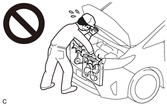
CAUTION:
To prevent injury due to contact with an operating V-ribbed belt or cooling fan, keep your hands and clothing away from the V-ribbed belt and cooling fans when working in the engine compartment with the engine running or the engine switch on (IG).
PROCEDURE
-
VISUALLY INSPECT HOSES, CONNECTIONS AND GASKETS
-
Check that the hoses and gaskets are not cracked or damaged, and that there are no air or oil leaks from connections.
Tech Tips
Cracked hoses and gaskets or loose connections may cause the engine to run improperly or stall.
-
-
INSPECT TURBOCHARGER SUB-ASSEMBLY
CAUTION:
To prevent injury due to contact with an operating V-ribbed belt or cooling fan, keep your hands and clothing away from the V-ribbed belt and cooling fans when working in the engine compartment with the engine running or the engine switch on (IG).
Note
Perform this procedure in a safe location with another person.
-
Start the engine and warm it up.
-
Connect the GTS to the DLC3.
-
Turn the engine switch on (IG).
-
Enter the following menus: Powertrain / Engine / Data List / Boost Pressure Sensor
Powertrain > Engine > Data ListTester Display Boost Pressure Sensor -
Fully accelerate the vehicle with the shift lever in 2nd and measure the boost pressure when the engine speed is 4000 rpm (approximately 60 km/h (39 mph)).
Standard Pressure 120 kPa (1.2 kgf/cm2, 17 psi) If the result is not as specified, check the waste gate valve actuator and turbocharger sub-assembly.
-
-
INSPECT TURBINE SHAFT
CAUTION:
To prevent injury due to contact with an operating V-ribbed belt or cooling fan, keep your hands and clothing away from the V-ribbed belt and cooling fans when working in the engine compartment with the engine running or the engine switch on (IG).
-
Remove the inlet compressor elbow.
-
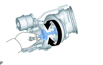
Rotate the compressor wheel by hand as shown in the illustration, and check that the compressor wheel rotates smoothly.
Note
If the compressor wheel does not rotate smoothly and there is interference between the turbine wheel and turbine housing with valve sub-assembly, replace the compressor housing with bearing sub-assembly and turbine housing with valve sub-assembly at the same time.
Tech Tips
If the compressor wheel does not rotate smoothly, replace the compressor housing with bearing sub-assembly.
-
Install the inlet compressor elbow.
-
-
INSPECT WASTE GATE VALVE ACTUATOR WITH BRACKET ASSEMBLY
CAUTION:
To prevent injury due to contact with an operating V-ribbed belt or cooling fan, keep your hands and clothing away from the V-ribbed belt and cooling fans when working in the engine compartment with the engine running or the engine switch on (IG).
-
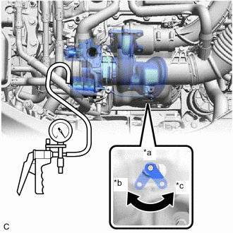
*a Exhaust Heat Insulator Check Window *b Link Position When Vacuum of 35 +/- 4.0 kPa (263 +/- 30 mmHg, 10.3 +/- 1.18 in. Hg) Applied *c Link Position When No Vacuum Applied 0 kPa (0 mmHg, 0 in. Hg) Using a vacuum pump, apply a vacuum of 35 +/- 4.0 kPa (263 +/- 30 mmHg, 10.3 +/- 1.18 in. Hg) to the diaphragm chamber and check that the waste gate valve actuator link moves as shown in the illustration through the exhaust heat insulator check window.
OK The waste gate valve actuator link moves as shown in the illustration. Note
Do not apply a vacuum of 65 kPa (488 mmHg, 19.2 in. Hg) or more to the waste gate valve actuator as doing so may damage the diaphragm.
Tech Tips
If the result is not as specified, check the waste gate valve actuator with bracket assembly and turbocharger sub-assembly.
-