SEAT HEATER SYSTEM TERMINALS OF ECU
-
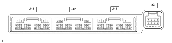
CHECK AIR CONDITIONING AMPLIFIER ASSEMBLY
-
Disconnect the J43 air conditioning amplifier assembly connector.
-
Measure the voltage and resistance according to the value(s) in the table below.
Tech Tips
Measure the values on the wire harness side with the connector disconnected.
Terminal No. (Symbol) Wiring Color Terminal Description Condition Specified Condition J43-2 (IG+) - Body ground GR - Body ground IG power supply Engine switch on (IG) 11 to 14 V J43-2 (IG+) - Body ground GR - Body ground IG power supply Engine switch off Below 1 V J43-4 (GND) - Body ground W-B - Body ground Ground Always Below 1 Ω -
Reconnect the J43 air conditioning amplifier assembly connector.
-
Measure the voltage and check for pulses according to the value(s) in the table below.
Terminal No. (Symbol) Wiring Color Terminal Description Condition Specified Condition J48-16 (SHP+) - J43-4 (GND) Y - W-B Refreshing seat switch volume signal
-
Engine switch on (IG)
-
Refreshing seat switch on (LO)
(heater position)
Below 1 V J48-15 (SHD+) -J43-4 (GND) P - W-B Refreshing seat switch volume signal
-
Engine switch on (IG)
-
Refreshing seat switch on (LO)
(heater position)
Below 1 V J43-14 (LIN1) - Body ground G - Body ground Refreshing seat switch signal Engine switch on (IG) Pulse generation -
-
-
CHECK REFRESHING SEAT SWITCH (FOR FRONT SIDE)

-
Disconnect the J82 refreshing seat switch connector.
-
Measure the voltage and resistance according to the value(s) in the table below.
Tech Tips
Measure the values on the wire harness side with the connector disconnected.
Terminal No. (Symbol) Wiring Color Terminal Description Condition Specified Condition J82-2 (IG) - Body ground L - Body ground IG power supply Engine switch on (IG) 11 to 14 V J82-2 (IG) - Body ground L - Body ground IG power supply Engine switch off Below 1 V J82-7 (E) - Body ground W-B - Body ground Ground Always Below 1 Ω -
Reconnect the J82 refreshing seat switch connector.
-
Check for pulses according to the value(s) in the table below.
Terminal No. (Symbol) Wiring Color Terminal Description Condition Specified Condition J82-4 (LIN1) - Body ground G - Body ground Refreshing seat switch signal Engine switch on (IG) Pulse generation
-
-
CHECK REFRESHING SEAT SWITCH (FOR REAR SIDE) (w/ Rear Seat Heater)

-
Disconnect the J15 refreshing seat switch connector.
-
Measure the voltage and resistance according to the value(s) in the table below.
Tech Tips
Measure the values on the wire harness side with the connector disconnected.
Terminal No. (Symbol) Wiring Color Terminal Description Condition Specified Condition J15-1 (IG) - Body ground LG - Body ground IG power supply Engine switch on (IG) 11 to 14 V J15-1 (IG) - Body ground LG - Body ground IG power supply Engine switch off Below 1 V J15-5 (E) - Body ground W-B - Body ground Ground Always Below 1 Ω -
Reconnect the J15 refreshing seat switch connector.
-
Check for pulses according to the value(s) in the table below.
Terminal No. (Symbol) Wiring Color Terminal Description Condition Specified Condition J15-3 (RLIN) - Body ground R - Body ground Refreshing seat switch signal Engine switch on (IG) Pulse generation
-