REAR TRACTION MOTOR INSTALLATION
PROCEDURE
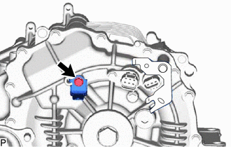
INSTALL BREATHER PLUG
CAUTION:Be sure to wear insulated gloves.
Install the breather plug to the rear traction motor with transaxle assembly.
20.6 N*m
210 kgf*cm
15 ft.*lbf
TEMPORARILY INSTALL FRONT DIFFERENTIAL SUPPORT ASSEMBLY
CAUTION:Be sure to wear insulated gloves.
Temporarily install the front differential support assembly to the rear traction motor with transaxle assembly with the 2 bolts.
INSTALL WIRE HARNESS CLAMP BRACKET
CAUTION:Wear insulated gloves and use insulated tools.
-
Install the wire harness clamp bracket to the rear traction motor with transaxle assembly with the bolt.
7.65 N*m
78 kgf*cm
68 in.*lbf
-
INSTALL DIFFERENTIAL MOUNT CUSHION
-
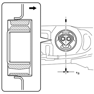
*a
-3 to 3°

Rear of vehicle
Temporarily install the differential mount cushion to the rear suspension member sub-assembly from the rear of the vehicle.
-
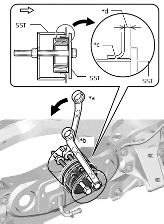
*a
Turn
*b
Hold
*c
Point of engagement with rear suspension member sub-assembly
*d
5.0 to 6.0 mm (0.1969 to 0.2362 in.)

Rear of vehicle
Using SST, install the differential mount cushion.(*1)
09570-48010
Note:Before using SST, apply grease to SST bolts.
Do not tilt the bolts of SST.
Tighten the 2 bolts of SST so that they enter the 2 holes of the rear No. 1 differential mount cushion by an equal amount.
-
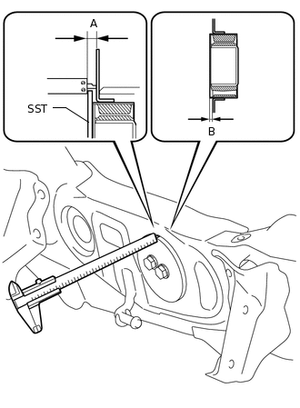
Using a vernier caliper, measure the distance labeled A in the illustration. (*2)
Note:Measure at several points to check that the differential mount cushion is uniformly inserted.
Measure at points where there is no welding bead.
Repeat steps *1 and *2 above to press the differential mount cushion into the rear suspension member sub-assembly until the distance labeled A in the illustration reaches the reference value.
Reference
11 to 12 mm (0.4331 to 0.4724 in.)
Remove SST, and then using a vernier caliper, measure the protrusion (labeled B in the illustration) of the differential mount cushion. Check that the measured value is within the specified range.
Standard
5.0 to 6.0 mm (0.1969 to 0.2362 in.)
-
INSTALL REAR TRACTION MOTOR WITH TRANSAXLE ASSEMBLY
Using an engine sling device and chain block, hold the rear traction motor with transaxle assembly.
CAUTION:As the rear traction motor with transaxle assembly is heavy, hold it securely using an engine sling device and chain block.
Note:Do not drop the rear traction motor with transaxle assembly.
Do not damage the installation surface of the rear traction motor with transaxle assembly.
-
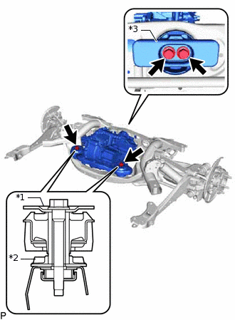
*1
Upper Differential Mount Stopper
*2
Lower Differential Mount Stopper
*3
Differential Dynamic Damper
Temporarily install the 2 upper differential mount stoppers, 2 lower differential mount stoppers, differential dynamic damper and rear traction motor with transaxle assembly to the rear suspension member sub-assembly with the 4 bolts.
-
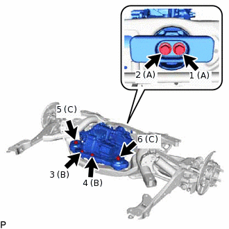
Tighten the 6 bolts in the order shown in the illustration.
for bolt A
95.1 N*m
970 kgf*cm
70 ft.*lbf
for bolt B
80 N*m
816 kgf*cm
59 ft.*lbf
for bolt C
86 N*m
877 kgf*cm
63 ft.*lbf
Remove the engine sling device.
INSTALL EXTENSION WIRE ASSEMBLY
CAUTION:Be sure to wear insulated gloves.
Install the extension wire assembly to the rear traction motor with transaxle assembly with the 3 bolts.
10 N*m
102 kgf*cm
7 ft.*lbf
Note:Firmly insert the extension wire assembly to the rear traction motor.
INSTALL REAR SUSPENSION MEMBER SUB-ASSEMBLY
CONNECT WIRE HARNESS
CAUTION:Wear insulated gloves and use insulated tools.
Connect the No. 2 frame wire to the rear traction motor with transaxle assembly and vehicle body with the 2 nuts.
15 N*m
153 kgf*cm
11 ft.*lbf
Attach the 5 clamps.
Connect the resolver sensor connector.
Connect the temperature sensor connector.
INSTALL REAR DRIVE SHAFT ASSEMBLY
INSTALL INVERTER RESERVE TANK ASSEMBLY
CONNECT WIRE HARNESS
ADD HYBRID TRANSAXLE FLUID
INSPECT HYBRID TRANSAXLE FLUID
INSTALL SERVICE PLUG GRIP