SEAT BELT WARNING SYSTEM TERMINALS OF ECU
CHECK COMBINATION METER ASSEMBLY

Disconnect the H62 combination meter assembly connector.
Measure the resistance and voltage according to the value(s) in the table below.
Terminal No. (Symbol)
Wiring Color
Terminal Description
Condition
Specified Condition
H62-40 (B) - Body ground
W - Body ground
Battery power supply
Always
11 to 14 V
H62-39 (IG+) - Body ground
P - Body ground
IG power supply
Ignition switch ON
11 to 14 V
Ignition switch off
Below 1 V
H62-21 (ET) - Body ground
BR - Body ground
Ground
Always
Below 1 Ω
Reconnect the H62 combination meter assembly connector.
Measure the voltage according to the value(s) in the table below.
Terminal No. (Symbol)
Wiring Color
Terminal Description
Condition
Specified Condition
H62-1 (RLMT) - Body ground*1
R - Body ground
Rear No. 1 seat belt LH warning light signal
Rear No. 1 seat belt LH fastened
11 to 14 V
Rear No. 1 seat belt LH unfastened
Below 1 V
H62-2 (RCMT) - Body ground*1
W - Body ground
Rear No. 1 seat center belt warning light signal
Rear No. 1 seat center belt fastened
11 to 14 V
Rear No. 1 seat center belt unfastened
Below 1 V
H62-4 (RRMT) - Body ground*1
B - Body ground
Rear No. 1 seat belt RH warning light signal
Rear No. 1 seat belt RH fastened
11 to 14 V
Rear No. 1 seat belt RH unfastened
Below 1 V
H62-9 (RLBT) - Body ground*2
G - Body ground
Rear No. 2 seat belt LH warning light signal
Rear No. 2 seat belt LH fastened
11 to 14 V
Rear No. 2 seat belt LH unfastened
Below 1 V
H62-11 (PKB1) - Body ground
L - Body ground
Front passenger seat belt signal
Front passenger seat occupied, seat belt fastened
Below 1 V
Front passenger seat occupied, seat belt unfastened
11 to 14 V
H62-13 (MSD) - Body ground*1
R - Body ground
Rear No. 1 seat belt LH signal
Rear No. 1 seat belt LH fastened
Below 1 V
Rear No. 1 seat belt LH unfastened
11 to 14 V
H62-14 (MSTI) - Body ground*1
W - Body ground
Rear No. 1 seat center belt signal
Rear No. 1 seat center belt fastened
Below 1 V
Rear No. 1 seat center belt unfastened
11 to 14 V
H62-15 (MSFM) - Body ground*1
B - Body ground
Rear No. 1 seat belt RH signal
Rear No. 1 seat belt RH fastened
Below 1 V
Rear No. 1 seat belt RH unfastened
11 to 14 V
H62-27 (RRBT) - Body ground*2
L - Body ground
Rear No. 2 seat belt RH warning light signal
Rear No. 2 seat belt RH fastened
11 to 14 V
Rear No. 2 seat belt RH unfastened
Below 1 V
H62-34 (MSM+) - Body ground*2
G - Body ground
Rear No. 2 seat belt LH signal
Rear No. 2 seat belt LH fastened
Below 1 V
Rear No. 2 seat belt LH unfastened
11 to 14 V
H62-35 (MS+) - Body ground*2
L - Body ground
Rear No. 2 seat belt RH signal
Rear No. 2 seat belt RH fastened
Below 1 V
Rear No. 2 seat belt RH unfastened
11 to 14 V
*1: w/ Rear No. 1 Seat
*2: w/ Rear No. 2 Seat
CHECK MAIN BODY ECU (INSTRUMENT PANEL JUNCTION BLOCK ASSEMBLY)
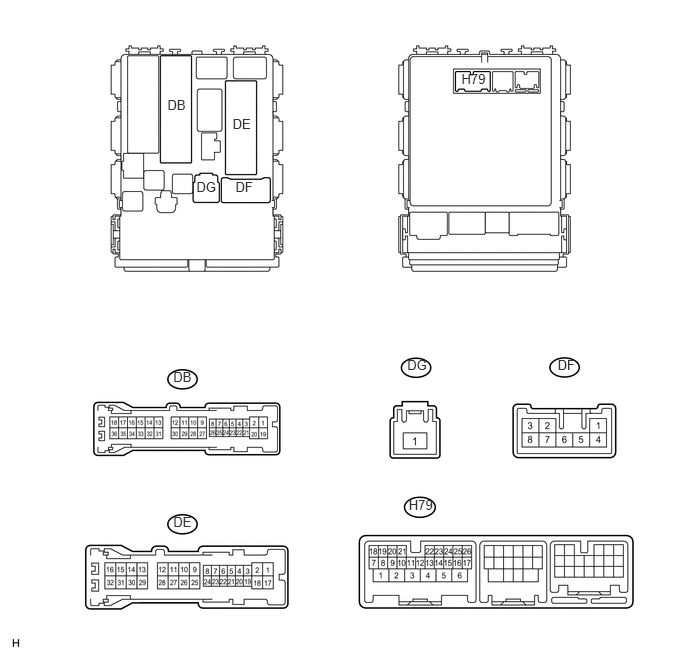
Disconnect the DB, DE, DF, DG and H79 main body ECU connectors.
Measure the resistance and voltage according to the value(s) in the table below.
Terminal No. (Symbol)
Wiring Color
Terminal Description
Condition
Specified Condition
DE-28 (GND1) - Body ground
W-B - Body ground
Ground
Always
Below 1 Ω
DG-1 (ALTB) - Body ground
W - Body ground
Battery (ECU power source)
Always
11 to 14 V
DB-30 (BECU) - Body ground
W - Body ground
Battery (ECU power source)
Always
11 to 14 V
DF-3 (IG) - Body ground
W - Body ground
IG power supply
Ignition switch ON
11 to 14 V
Ignition switch off
Below 1 V
DF-5 (ACC) - Body ground
W - Body ground
ACC power supply
Ignition switch ACC
11 to 14 V
Ignition switch off
Below 1 V
H79-8 (LCTY) - Body ground
SB - Body ground
Rear door courtesy light switch LH signal
Rear door LH open
Below 1 Ω
Rear door LH closed
10 kΩ or higher
DE-19 (RCTY) - Body ground
LG - Body ground
Rear door courtesy light switch RH signal
Rear door RH open
Below 1 Ω
Rear door RH closed
10 kΩ or higher
Reconnect the DB, DE, DF, DG and H79 main body ECU connectors.
Measure the voltage according to the value(s) in the table below.
Terminal No. (Symbol)
Wiring Color
Terminal Description
Condition
Specified Condition
H79-26 (DBKL) - Body ground
P - Body ground
Driver seat belt warning signal
Driver seat belt fastened
11 to 14 V
Driver seat belt unfastened
Below 1 V