IMMOBILISER SYSTEM(w/ Entry and Start System) TERMINALS OF ECU
-
CHECK ENGINE SWITCH

-
Measure the resistance and voltage according to the value(s) in the table below.
Terminal No. (Symbol) Input/Output Wiring Color Terminal Description Condition Specified Condition Related Data List Item/DTC G81-6 (AGND) - Body ground - SB - Body ground Transponder key amplifier ground Always Below 1 Ω - G81-7 (TXCT) - G81-6 (AGND) Input R - SB Immobiliser communication input Engine switch off, brake pedal*1 or clutch pedal*2 not depressed, 30 seconds or more elapsed after driver door opened and then closed Below 1 V - G81-8 (CODE) - G81-6 (AGND) Output Y - SB Immobiliser communication output Engine switch off, brake pedal*1 or clutch pedal*2 not depressed, 30 seconds or more elapsed after driver door opened and then closed Below 1 V - G81-10 (VC5) - G81-6 (AGND) Input LG - SB Transponder key amplifier power supply Engine switch off, brake pedal*1 or clutch pedal*2 not depressed, 30 seconds or more elapsed after driver door opened and then closed Below 1 V -
-
*1: for Automatic Transmission
-
*2: for Manual Transmission
-
-
Check for pulses according to the value(s) in the table below.
Terminal No. (Symbol) Input/Output Wiring Color Terminal Description Condition Specified Condition Related Data List Item/DTC G81-7 (TXCT) - G81-6 (AGND) Input R - SB Signal input from certification ECU (smart key ECU assembly)
(Code sent from certification ECU (smart key ECU assembly) to transponder key amplifier built into engine switch, and then transmitted by transponder key amplifier antenna as radio waves)
Engine switch off, key not in cabin, within 30 seconds after engine switch pressed Pulse generation
(See waveform 1)
-
BCC Malfunction
-
Abnormal Status
-
Different Encrypt Code
-
Different Serial Number
-
Frame Error
-
Response
Tech Tips
If immobiliser key code verification communication is not performed correctly, the malfunction may be indicated by one or more of the Data List items listed above
G81-8 (CODE) - G81-6 (AGND) Output Y - SB Signal output to certification ECU (smart key ECU assembly)
(Radio waves from transponder key amplifier built into engine switch used to detect key information. Key information then sent to certification ECU (smart key ECU assembly).)
Engine switch off, engine switch pressed with key held near engine switch* Pulse generation
(See waveform 2)
G81-10 (VC5) - G81-6 (AGND) Input LG - SB Transponder key amplifier power supply
(Power supplied from certification ECU (smart key ECU assembly) when transponder key amplifier built into engine switch activated)
Engine switch off, key not in cabin, within 30 seconds after engine switch pressed Pulse generation
(See waveform 3)
Tech Tips
*: Remove the key battery before performing this inspection.
-
-
Using an oscilloscope, check the waveform.
Tech Tips
The waveform shown in the illustration is an example for reference only. Noise, chattering, etc. are not shown.
-

Waveform 1 (Reference)
Measurement Condition Item Content Tester Connection G81-7 (TXCT) - G81-6 (AGND) Tool Setting 2 V/DIV., 20 ms./DIV. Condition Engine switch off, key not in cabin, within 30 seconds after engine switch pressed -
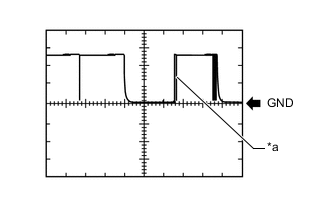
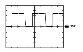
*a Key held near engine switch Waveform 2 (Reference)
Measurement Condition Item Content Tester Connection G81-8 (CODE) - G81-6 (AGND) Tool Setting 2 V/DIV., 20 ms./DIV. Condition Engine switch off, engine switch pressed with key held near engine switch* Tech Tips
*: Remove the key battery before performing this inspection.
-

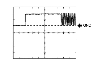
Waveform 3 (Reference)
Measurement Condition Item Content Tester Connection G81-10 (VC5) - G81-6 (AGND) Tool Setting 2 V/DIV., 200 ms./DIV. Condition Engine switch off, key not in cabin, within 30 seconds after engine switch pressed
-
-
-
CHECK CERTIFICATION ECU (SMART KEY ECU ASSEMBLY)
-
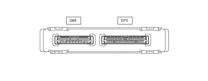
Disconnect the G69 and G70 certification ECU (smart key ECU assembly) connectors.
-
Measure the voltage and resistance according to the value(s) in the table below.
Terminal No. (Symbol) Input/Output Wiring Color Terminal Description Condition Specified Condition Related Data List Item/DTC G69-1 (+B) - G69-10 (E) Input P - BR +B power supply Always 11 to 14 V - G70-33 (CUTB) - G69-10 (E) Input W - BR Stand-by power Always 11 to 14 V - G69-10 (E) - Body ground - BR - Body ground Ground Always Below 1 Ω - -
Reconnect the G69 and G70 certification ECU (smart key ECU assembly) connectors.
-
Measure the resistance, voltage and check for pulses according to the value(s) in the table below.
Terminal No. (Symbol) Input/Output Wiring Color Terminal Description Condition Specified Condition Related Data List Item/DTC G69-15 (IND) - G69-10 (E) Output Y - BR Security indicator light output Engine switch off → on (IG) Pulse generation
→ Below 2 V
- G70-2 (TXCT) - G69-24 (AGND) Output R - SB Signal output to transponder key amplifier Engine switch off, brake pedal*1 or clutch pedal*2 not depressed, 30 seconds or more elapsed after driver door opened and then closed Below 1 V
-
BCC Malfunction
-
Abnormal Status
-
Different Encrypt Code
-
Different Serial Number
-
Frame Error
-
Response
G70-1 (CODE) - G69-24 (AGND) Input Y - SB Signal input from transponder key amplifier Engine switch off, brake pedal*1 or clutch pedal*2 not depressed, 30 seconds or more elapsed after driver door opened and then closed Below 1 V G70-20 (VC5) - G69-24 (AGND) Output LG - SB Transponder key amplifier power supply Engine switch off, brake pedal*1 or clutch pedal*2 not depressed, 30 seconds or more elapsed after driver door opened and then closed Below 1 V G69-24 (AGND) - Body ground - SB - Body ground Transponder key amplifier ground Always Below 1 Ω
-
*1: for Automatic Transmission
-
*2: for Manual Transmission
-
-
Measure the voltage and check for pulses according to the value(s) in the table below.
Terminal No. (Symbol) Input/Output Wiring Color Terminal Description Condition Specified Condition Related Data List Item/DTC G70-2 (TXCT) - G69-24 (AGND) Output R - SB Signal output to transponder key amplifier
(Code sent from certification ECU (smart key ECU assembly) to transponder key amplifier built into engine switch, and then transmitted by transponder key amplifier antenna as radio waves)
Engine switch off, key not in cabin, within 30 seconds after engine switch pressed Pulse generation
(See waveform 1)
-
BCC Malfunction
-
Abnormal Status
-
Different Encrypt Code
-
Different Serial Number
-
Frame Error
-
Response
G70-1 (CODE) - G69-24 (AGND) Input Y - SB Signal input from transponder key amplifier
(Radio waves from transponder key amplifier built into engine switch used to detect key information. Key information then sent to certification ECU (smart key ECU assembly).)
Engine switch off, engine switch pressed with key held near engine switch*1 Pulse generation
(See waveform 2)
G70-20 (VC5) - G69-24 (AGND) Output LG - SB Transponder key amplifier power supply
(Power supplied from certification ECU (smart key ECU assembly) when transponder key amplifier built into engine switch activated)
Engine switch off, key not in cabin, within 30 seconds after engine switch pressed Pulse generation
(See waveform 3)
G69-3 (EFII) - G69-24 (AGND)*2 Input Y - SB EFI communication input
(Signal input from ECM to certification ECU (smart key ECU assembly))
Engine switch off 11 to 14 V
-
B2799
-
B279A
-
Engine Start Request
-
EFI Code Receive
G69-3 (EFII) - G69-24 (AGND)*2 Input Y - SB EFI communication input
(Signal input from ECM to certification ECU (smart key ECU assembly))
Within 3 seconds of engine start or within 3 seconds of engine switch turned on (IG) after battery cable disconnected and reconnected Pulse generation
(See waveform 4)
G70-35 (EFIO) - G69-24 (AGND)*2 Output B - SB EFI communication output
(Signal output from certification ECU (smart key ECU assembly) to ECM)
Engine switch off Below 1 V G70-35 (EFIO) - G69-24 (AGND)*2 Output B - SB EFI communication output
(Signal output from certification ECU (smart key ECU assembly) to ECM)
Within 3 seconds of engine start or within 3 seconds of engine switch turned on (IG) after battery cable disconnected and reconnected Pulse generation
(See waveform 5)
Tech Tips
*1: Remove the key battery before performing this inspection.
-
*2: w/o ID Code Box (Immobiliser Code ECU)
-
-
Using an oscilloscope, check the waveform.
Tech Tips
The waveform shown in the illustration is an example for reference only. Noise, chattering, etc. are not shown.
-
Waveform 1 (Reference)
Measurement Condition Item Content Tester Connection G70-2 (TXCT) - G69-24 (AGND) Tool Setting 2 V/DIV., 20 ms./DIV. Condition Engine switch off, key not in cabin, within 30 seconds after engine switch pressed -
*a Key held near engine switch Waveform 2 (Reference)
Measurement Condition Item Content Tester Connection G70-1 (CODE) - G69-24 (AGND) Tool Setting 2 V/DIV., 20 ms./DIV. Condition Engine switch off, engine switch pressed with key held near engine switch* Tech Tips
*: Remove the key battery before performing this inspection.
-
Waveform 3 (Reference)
Measurement Condition Item Content Tester Connection G70-20 (VC5) - G69-24 (AGND) Tool Setting 2 V/DIV., 200 ms./DIV. Condition Engine switch off, key not in cabin, within 30 seconds after engine switch pressed -
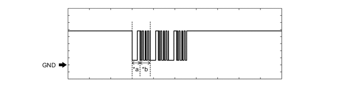
Waveform 4 (Reference)
*a Approximately 160 ms *b Approximately 270 ms Measurement Condition Item Content Tester Connection G69-3 (EFII) - G69-24 (AGND) Tool Setting 2 V/DIV., 500 ms./DIV. Condition Within 3 seconds of engine start or within 3 seconds of engine switch turned on (IG) after battery cable disconnected and reconnected -
Waveform 5 (Reference)
*a Approximately 160 ms *b Approximately 270 ms Measurement Condition Item Content Tester Connection G70-35 (EFIO) - G69-24 (AGND) Tool Setting 2 V/DIV., 500 ms./DIV. Condition Within 3 seconds of engine start or within 3 seconds of engine switch turned on (IG) after battery cable disconnected and reconnected
-
-
-
CHECK ID CODE BOX (IMMOBILISER CODE ECU) (w/ ID Code Box (Immobiliser Code ECU)
-
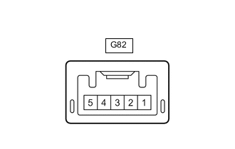
Disconnect the G82 ID code box (immobiliser code ECU) connector.
-
Measure the voltage and resistance according to the value(s) in the table below.
Terminal No. (Symbol) Input/Output Wiring Color Terminal Description Condition Specified Condition Related Data List Item/DTC G82-1 (+B) - Body ground Input L - Body ground +B power supply Always 11 to 14 V B2789 G82-5 (GND) - Body ground - BR - Body ground Ground Always Below 1 Ω B2789 -
Reconnect the G82 ID code box (immobiliser code ECU) connector.
-
Measure the voltage and check the pulse according to the value(s) in the table below.
Terminal No. (Symbol) Input/Output Wiring Color Terminal Description Condition Specified Condition Related Data List Item/DTC G82-3 (EFII) - G82-5 (GND) Input Y - BR EFI communication input (Signal input from ECM to certification ECU [smart key ECU assembly]) Engine switch off 11 to 14 V
-
B2799
-
B279A
-
Engine Start Request
-
EFI Code Receive
G82-4 (EFIO) - G82-5 (GND) Output B - BR EFI communication output (Signal output from certification ECU [smart key ECU assembly] to ECM) Engine switch off Below 1 V G82-3 (EFII) - G82-5 (GND) Input Y - BR EFI communication input (Signal input from ECM to certification ECU [smart key ECU assembly]) Within 3 seconds of engine start or within 3 seconds of engine switch turned on (IG) after battery cable disconnected and reconnected Pulse generation (See waveform 1) G82-4 (EFIO) - G82-5 (GND) Output B - BR EFI communication output (Signal output from certification ECU [smart key ECU assembly] to ECM) Within 3 seconds of engine start or within 3 seconds of engine switch turned on (IG) after battery cable disconnected and reconnected Pulse generation (See waveform 2) -
-
Inspect using an oscilloscope.
Note
The waveform shown in the illustration is an example for reference only. Noise, chattering, etc. are not shown.
-
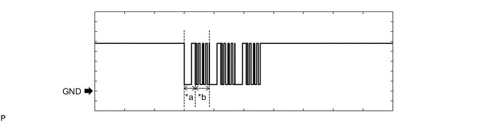
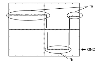
Waveform 1 (Reference)
*a Approximately 160 ms *b Approximately 270 ms Measurement Condition Item Content Tester Connection G82-3 (EFII) - G82-5 (GND) Tool Setting 2 V/DIV., 500 ms./DIV. Condition Within 3 seconds of engine start or within 3 seconds of engine switch turned on (IG) after battery cable disconnected and reconnected -
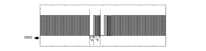
Waveform 2 (Reference)
*a Approximately 160 ms *b Approximately 270 ms Measurement Condition Item Content Tester Connection G82-4 (EFIO) - G82-5 (GND) Tool Setting 2 V/DIV., 500 ms./DIV. Condition Within 3 seconds of engine start or within 3 seconds of engine switch turned on (IG) after battery cable disconnected and reconnected
-
-
-
CHECK STEERING LOCK ECU (STEERING LOCK ACTUATOR ASSEMBLY)

-
Measure the voltage, resistance and check for pulses to the value(s) in the table below.
Terminal No. (Symbol) Input/Output Wiring Color Terminal Description Condition Specified Condition Related Data List Item/DTC G71-1 (GND) - Body ground - W-B - Body ground Ground Always Below 1 Ω - G71-3 (IGE) - G71-1 (GND) Input L - W-B Steering lock motor operation permission signal (motor operation permission signal supplied by certification ECU (smart key ECU assembly)) Steering lock motor operates when both conditions met, and then door opened:
-
Shift lever in P*1
-
Key carried, engine switch turned on (IG), steering unlocked, and then engine switch turned off
Pulse generation
(See waveform 1)
-
Power Supply Short
-
Unlock Request Receive
-
Lock Request Receive
G71-4 (SLP1) - G71-1 (GND) Output R - W-B Steering lock bar position signal (signal output from steering unlock sensor) Steering locked → unlocked*2 11 to 14 V → Below 1.5 V
-
Push Start Error
-
Sensor Value
G71-6 (IG2) - G71-1 (GND) Input P - W-B IG signal (IG2 power supply input for steering lock motor) Engine switch off → on (IG) Below 1 V → 11 to 14 V B2788 G71-7 (B) - Body ground Output W - Body ground Constant power supply Always 11 to 14 V B2788
-
*1: for Automatic Transmission
If the result is not as specified, the steering lock ECU (steering lock actuator assembly) may be malfunctioning.
Tech Tips
*2: The steering locks when any door is opened with the shift lever in P*1 and the engine switch off. The steering unlocks when the engine switch is turned on (ACC).
-
-
Using an oscilloscope, check the waveform.
Tech Tips
The waveform shown in the illustration is an example for reference only. Noise, chattering, etc. are not shown.
-
*a Steering lock motor not operating *b Steering lock motor operating Waveform 1 (Reference)
Measurement Condition Item Content Tester Connection G71-3 (IGE) - G71-1 (GND) Tool Setting 2 V/DIV., 20 ms./DIV. Condition Steering lock motor operates when both conditions met, and then door opened:
-
Shift lever in P*
-
Key carried, engine switch turned on (IG), steering unlocked, and then engine switch turned off
-
*: for Automatic Transmission
-
-
-
-
CHECK ECM (for 2TR-FE)
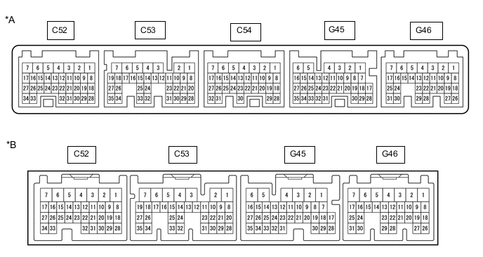
*A for Automatic Transmission *B for Manual Transmission
-
Measure the resistance, voltage and check for pulses according to the value(s) in the table below.
Tester Connection Input/Output Wiring Color Terminal Description Condition Specified Condition Related Data List Item C52-3 (E1) - Body ground - W-B - Body ground Ground Always Below 1 Ω - C52-4 (ME01) - Body ground - W-B - Body ground Ground Always Below 1 Ω - C52-1 (E01) - Body ground - W-B - Body ground Ground Always Below 1 Ω - C53-5 (E04) - Body ground - W-B - Body ground Ground Always Below 1 Ω - C52-2 (E02) - Body ground - W-B - Body ground Ground Always Below 1 Ω - G46-1 (+B) - C52-3 (E1) Input L - W-B IG power supply Engine switch on (IG) 11 to 14 V - G46-2 (+B2) - C52-3 (E1) Input B - W-B IG power supply Engine switch on (IG) 11 to 14 V - G46-3 (BATT) - C52-3 (E1) Input Y - W-B +B power supply Always 11 to 14 V - G45-9 (IMO) - C52-3 (E1) Output Y - W-B Certification ECU (smart key ECU assembly) communication output Engine switch off 11 to 14 V E/G Start Permission Within 3 seconds of starter operation and initial combustion, or within 3 seconds of engine switch first being turned on (IG) after cable disconnected and reconnected to negative (-) battery terminal Pulse generation
(See waveform 1)
E/G Start Permission G45-10 (IMI) - C52-3 (E1) Input B - W-B Certification ECU (smart key ECU assembly) communication input Engine switch off Below 1 V E/G Start Permission Within 3 seconds of starter operation and initial combustion, or within 3 seconds of engine switch first being turned on (IG) after cable disconnected and reconnected to negative (-) battery terminal Pulse generation
(See waveform 2)
E/G Start Permission -
Using an oscilloscope, check the waveform.
-
Waveform 1 (Reference)
*a Approximately 160 ms *b Approximately 270 ms Tester Connection G45-9 (IMO) - C52-3 (E1) Tool Setting 2 V/DIV., 500 ms./DIV. Condition Within 3 seconds of starter operation and initial combustion, or within 3 seconds of engine switch first being turned on (IG) after cable disconnected and reconnected to negative (-) battery terminal -
Waveform 2 (Reference)

*a Approximately 160 ms *b Approximately 270 ms Tester Connection G45-10 (IMI) - C52-3 (E1) Tool Setting 2 V/DIV., 500 ms./DIV. Condition Within 3 seconds of starter operation and initial combustion, or within 3 seconds of engine switch first being turned on (IG) after cable disconnected and reconnected to negative (-) battery terminal
-
-
-
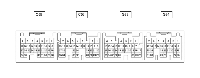
CHECK ECM (for 2KD-FTV)
-
Measure the resistance, voltage and check for pulses according to the value(s) in the table below.
Terminal No. (Symbol) Input/Output Wiring Color Terminal Description Condition Specified Condition Related Data List Item/DTC C56-7 (E1) - Body ground - W-B - Body ground Ground Always Below 1 Ω - G83-2 (BATT) - C56-7 (E1) Input Y - W-B +B power supply Always 11 to 14 V - G84-1 (+B) - C56-7 (E1) Input L - W-B IG power supply Engine switch on (IG) 11 to 14 V - G83-29 (IMO) - C56-7 (E1) Output Y - W-B Certification ECU (smart key ECU assembly) communication output Engine switch off 11 to 14 V - Within 3 seconds of engine start or within 3 seconds of engine switch turned on (IG) after battery cable disconnected and reconnected Pulse generation
(See waveform 1)
- G83-30 (IMI) - C56-7 (E1) Input B - W-B Certification ECU (smart key ECU assembly) communication input Engine switch off Below 1 V - Within 3 seconds of engine start or within 3 seconds of engine switch turned on (IG) after battery cable disconnected and reconnected Pulse generation
(See waveform 2)
- -
Using an oscilloscope, check the waveform.
Tech Tips
The waveform shown in the illustration is an example for reference only. Noise, chattering, etc. are not shown.
-
Waveform 1 (Reference)
*a Approximately 160 ms *b Approximately 270 ms Measurement Condition Item Content Tester Connection G83-29 (IMO) - C56-7 (E1) Tool Setting 2 V/DIV., 500 ms./DIV. Condition Within 3 seconds of engine start or within 3 seconds of engine switch turned on (IG) after battery cable disconnected and reconnected -
Waveform 2 (Reference)
*a Approximately 160 ms *b Approximately 270 ms Measurement Condition Item Content Tester Connection G83-30 (IMI) - C56-7 (E1) Tool Setting 2 V/DIV., 500 ms./DIV. Condition Within 3 seconds of engine start or within 3 seconds of engine switch turned on (IG) after battery cable disconnected and reconnected
-
-
-
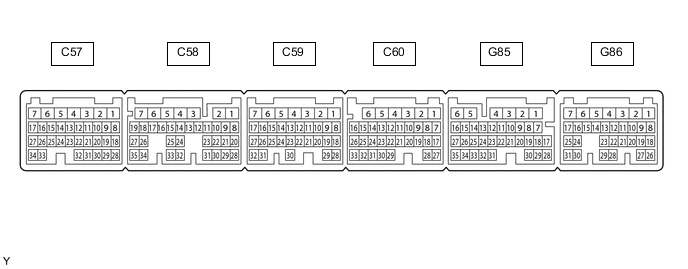
CHECK ECM (for 1GD-FTV, 2GD-FTV)
-
Measure the resistance, voltage and check for pulses according to the value(s) in the table below.
Terminal No. (Symbol) Input/Output Wiring Color Terminal Description Condition Specified Condition Related Data List Item/DTC C60-1 (E1) - Body ground - W-B - Body ground Ground Always Below 1 Ω - G86-1 (BATT) - C60-1 (E1) Input Y - W-B +B power supply Always 11 to 14 V - G86-2 (+B) - C60-1 (E1) Input L - W-B IG power supply Engine switch on (IG) 11 to 14 V - G86-3 (+B2) - C60-1 (E1) Input B - W-B IG power supply Engine switch on (IG) 11 to 14 V - G86-17 (IMO) - C60-1 (E1) Output Y - W-B Certification ECU (smart key ECU assembly) communication output*1
ID code box (immobiliser code ECU) communication output*2
Engine switch off 11 to 14 V - Within 3 seconds of engine start or within 3 seconds of engine switch turned on (IG) after battery cable disconnected and reconnected Pulse generation
(See waveform 1)
- G86-16 (IMI) - C60-1 (E1) Input B - W-B Certification ECU (smart key ECU assembly) communication input*1
ID code box (immobiliser code ECU) communication input*2
Engine switch off Below 1 V - Within 3 seconds of engine start or within 3 seconds of engine switch turned on (IG) after battery cable disconnected and reconnected Pulse generation
(See waveform 2)
- *1: w/o ID Code Box (Immobiliser Code ECU)
*2: w/ ID Code Box (Immobiliser Code ECU)
-
Using an oscilloscope, check the waveform.
Tech Tips
The waveform shown in the illustration is an example for reference only. Noise, chattering, etc. are not shown.
-
Waveform 1 (Reference)
*a Approximately 160 ms *b Approximately 270 ms Measurement Condition Item Content Tester Connection G86-17 (IMO) - C60-1 (E1) Tool Setting 2 V/DIV., 500 ms./DIV. Condition Within 3 seconds of engine start or within 3 seconds of engine switch turned on (IG) after battery cable disconnected and reconnected -
Waveform 2 (Reference)
*a Approximately 160 ms *b Approximately 270 ms Measurement Condition Item Content Tester Connection G86-16 (IMI) - C60-1 (E1) Tool Setting 2 V/DIV., 500 ms./DIV. Condition Within 3 seconds of engine start or within 3 seconds of engine switch turned on (IG) after battery cable disconnected and reconnected
-
-
-
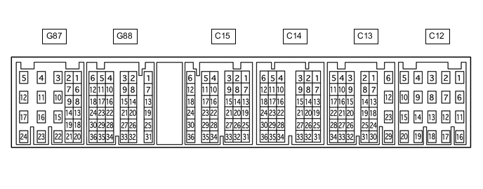
CHECK ECM (for 1GR-FE)
-
Measure the resistance, voltage and check for pulses according to the value(s) in the table below.
Tester Connection Input/Output Wiring Color Terminal Description Condition Specified Condition Related Data List Item C13-12 (E1) - Body ground - BR - Body ground Ground Always Below 1 Ω - C13-29 (ME01) - Body ground - W-B - Body ground Ground Always Below 1 Ω - C13-23 (E01) - Body ground - W-B - Body ground Ground Always Below 1 Ω - C12-16 (E04) - Body ground - W-B - Body ground Ground Always Below 1 Ω - C12-14 (E02) - Body ground - W-B - Body ground Ground Always Below 1 Ω - G87-23 (+B) - C13-12 (E1) Input L - BR IG power supply Engine switch on (IG) 11 to 14 V - G87-22 (+B2) - C13-12 (E1) Input B - BR IG power supply Engine switch on (IG) 11 to 14 V - G87-24 (BATT) - C13-12 (E1) Input Y - BR +B power supply Always 11 to 14 V - G88-8 (IMO) - C13-12 (E1) Output Y - BR Certification ECU (smart key ECU assembly) communication output*1
ID code box (immobiliser code ECU) communication output*2
Engine switch off 11 to 14 V E/G Start Permission Within 3 seconds of starter operation and initial combustion, or within 3 seconds of engine switch first being turned on (IG) after cable disconnected and reconnected to negative (-) battery terminal Pulse generation
(See waveform 1)
E/G Start Permission G88-10 (IMI) - C13-12 (E1) Input B - BR Certification ECU (smart key ECU assembly) communication input*1
ID code box (immobiliser code ECU) communication input*2
Engine switch off Below 1 V E/G Start Permission Within 3 seconds of starter operation and initial combustion, or within 3 seconds of engine switch first being turned on (IG) after cable disconnected and reconnected to negative (-) battery terminal Pulse generation
(See waveform 2)
E/G Start Permission *1: w/o ID Code Box (Immobiliser Code ECU)
*2: w/ ID Code Box (Immobiliser Code ECU)
-
Using an oscilloscope, check the waveform.
-
Waveform 1 (Reference)
*a Approximately 160 ms *b Approximately 270 ms Tester Connection G88-8 (IMO) - C13-12 (E1) Tool Setting 2 V/DIV., 500 ms./DIV. Condition Within 3 seconds of starter operation and initial combustion, or within 3 seconds of engine switch first being turned on (IG) after cable disconnected and reconnected to negative (-) battery terminal -
Waveform 2 (Reference)
*a Approximately 160 ms *b Approximately 270 ms Tester Connection G88-10 (IMI) - C13-12 (E1) Tool Setting 2 V/DIV., 500 ms./DIV. Condition Within 3 seconds of starter operation and initial combustion, or within 3 seconds of engine switch first being turned on (IG) after cable disconnected and reconnected to negative (-) battery terminal
-
-