LIGHTING SYSTEM IG Signal Circuit
| DTC Code | DTC Name |
|---|---|
| IG Signal Circuit |
DESCRIPTION
The main body ECU receives an ignition switch signal used to control the exterior light control system for automatic light control*1, light auto turn off control and daytime running light control*2.
*1: w/ Automatic Light Control System
*2: w/ Daytime Running Light System
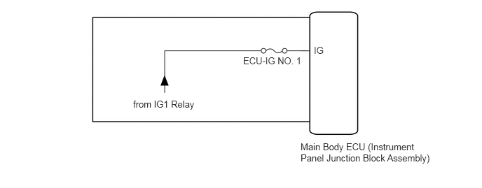
WIRING DIAGRAM
CAUTION / NOTICE / HINT
Inspect the fuses for circuits related to this system before performing the following inspection procedure.
PROCEDURE
READ VALUE USING INTELLIGENT TESTER
Using the intelligent tester, read the Data List (Click here).
Table 1. Main Body Tester Display
Measurement Item/Range
Normal Condition
Diagnostic Note
IG SW
Ignition switch ON signal / ON or OFF
ON: Ignition switch ON
OFF: Ignition switch off
-
OK
The display is as specified in the normal condition column.
CHECK HARNESS AND CONNECTOR (IG POWER SOURCE CIRCUIT)
-
Measure the voltage according to the value(s) in the table below.
Standard Voltage
Tester Connection
Switch Condition
Specified Condition
ECU-IG NO. 1 fuse terminal - Body ground
Ignition switch off
Below 1 V
Ignition switch ON
11 to 14 V
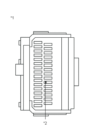
Table 2. Text in Illustration *1
Main Body ECU (Instrument Panel Junction Block Assembly)
*2
ECU-IG NO. 1 Fuse
REPLACE MAIN BODY ECU (INSTRUMENT PANEL JUNCTION BLOCK ASSEMBLY)
REPAIR OR REPLACE HARNESS OR CONNECTOR
-