ENGINE UNIT INSTALLATION
PROCEDURE
INSTALL NOISE FILTER
for Bank 2:
Install the noise filter to the cylinder head cover with the bolt.
10 N*m
102 kgf*cm
7 ft.*lbf
for Bank 1:
Install the noise filter to the cylinder head cover with the bolt.
10 N*m
102 kgf*cm
7 ft.*lbf
INSTALL IGNITION COIL ASSEMBLY
Install the 8 ignition coils with the 8 bolts.
10 N*m
102 kgf*cm
7 ft.*lbf
INSTALL NO. 11 WATER BY-PASS HOSE
-
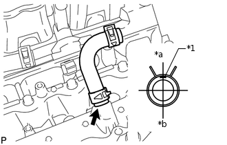
*1
Paint Mark
*a
Rear
*b
Front
Install the No. 11 water by-pass hose.
Tip:When connecting the hose, make sure the paint marks and clips are as shown in the illustration.
The direction of the hose clamp is indicated in the illustration.
-
INSTALL ENGINE WIRE
Attach the 3 wire harness clamps to install the engine wire.
Connect the 4 knock sensor connectors.
Install the bolt.
8.0 N*m
82 kgf*cm
71 in.*lbf
INSTALL NO. 1 ENGINE COVER
INSTALL NO. 2 ENGINE COVER
INSTALL SEPARATOR CASE
INSTALL NO. 1 IDLER PULLEY SUB-ASSEMBLY
INSTALL WATER PUMP PULLEY
INSTALL NO. 1 WATER BY-PASS HOSE
INSTALL NO. 3 ENGINE COVER
INSTALL NO. 4 ENGINE COVER
INSTALL NO. 2 FUEL DELIVERY PIPE SUB-ASSEMBLY
INSTALL FUEL DELIVERY PIPE SUB-ASSEMBLY
INSTALL FRONT NO. 1 ENGINE MOUNTING BRACKET LH
Install the front No. 1 engine mounting bracket LH with the 4 bolts.
35 N*m
357 kgf*cm
26 ft.*lbf
INSTALL FRONT NO. 1 ENGINE MOUNTING BRACKET RH
Install the front No. 1 engine mounting bracket RH with the 4 bolts.
35 N*m
357 kgf*cm
26 ft.*lbf
INSTALL EGR COOLER ASSEMBLY
CONNECT NO. 11 WATER BY-PASS HOSE
INSTALL NO. 8 WATER BY-PASS HOSE
-
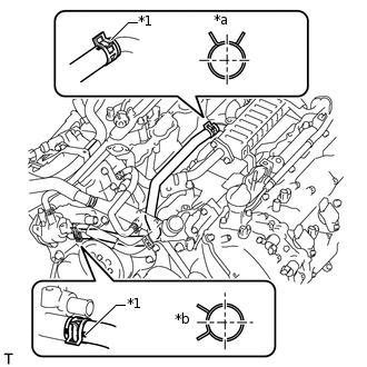
*1
Paint Mark
*a
Upper Side
*b
Front
Install the No. 8 water by-pass hose.
Tip:When connecting the hose, make sure the paint marks and clips are as shown in the illustration.
The direction of each hose clamp is indicated in the illustration.
-
INSTALL NO. 2 WATER BY-PASS PIPE
-
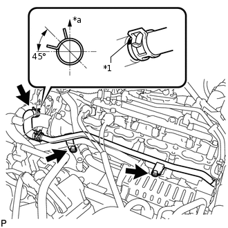
*1
Paint Mark
*a
Upper Side
Install the No. 2 water by-pass pipe with the 2 bolts and connect the hose.
10 N*m
102 kgf*cm
7 ft.*lbf
Tip:When connecting the hose, make sure the paint marks and clips are as shown in the illustration.
The direction of each hose clamp is indicated in the illustration.
-
INSTALL NO. 3 AIR TUBE
Install the No. 3 air tube with the bolt.
10 N*m
102 kgf*cm
7 ft.*lbf
INSTALL NO. 4 AIR TUBE
Install the No. 4 air tube with the bolt.
10 N*m
102 kgf*cm
7 ft.*lbf
INSTALL NO. 3 WATER BY-PASS HOSE
INSTALL NO. 3 WATER BY-PASS PIPE
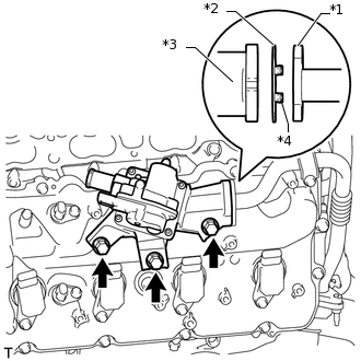
INSTALL AIR SWITCHING VALVE ASSEMBLY (for Bank 2)
-
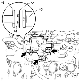
*1
No. 3 Air Tube
*2
New Gasket
*3
Air Switching Valve
*4
Claw
Install a new gasket and the air switching valve with the 3 bolts.
24 N*m
245 kgf*cm
18 ft.*lbf
Note:Make sure the gasket's claws are not caught between the air switching valve and No. 3 air tube.
Install the 2 bolts.
10 N*m
102 kgf*cm
7 ft.*lbf
Install the 2 wire harness clamp brackets with the 2 bolts.
8.0 N*m
82 kgf*cm
71 in.*lbf
-
INSTALL AIR SWITCHING VALVE ASSEMBLY (for Bank 1)
-
*1
No. 4 Air Tube
*2
New Gasket
*3
Air Switching Valve
*4
Claw
Install a new gasket and the air switching valve with the 3 bolts.
24 N*m
245 kgf*cm
18 ft.*lbf
Note:Make sure the gasket's claws are not caught between the air switching valve and No. 4 air tube.
Install the 2 bolts.
10 N*m
102 kgf*cm
7 ft.*lbf
Install the 2 wire harness clamp brackets with the 2 bolts.
8.0 N*m
82 kgf*cm
71 in.*lbf
-
INSTALL NO. 2 FUEL TUBE SUB-ASSEMBLY
Attach the clamp and install the No. 2 fuel tube (Click here).
Install the bolt.
10 N*m
102 kgf*cm
7 ft.*lbf
INSTALL FUEL HOSE
Attach the clamp and install the fuel hose (Click here).
INSTALL ENGINE WIRE