SHIFT AND SELECT ACTUATOR INSTALLATION
PROCEDURE
INSTALL SHIFT AND SELECT ACTUATOR ASSEMBLY
Install the breather plug cap to the shift and select actuator assembly.
Install the breather protector to the shift and select actuator assembly with the bolt.
18 N*m
184 kgf*cm
13 ft.*lbf
-
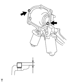
Using a plastic hammer, tap in 2 new ring pins to the specified protrusion height.
Protrusion Height
5.2 to 5.8 mm (0.205 to 0.228 in.)
Clean and degrease the contact surfaces between the shift and select actuator and front transaxle case.
-
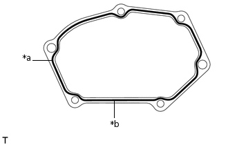
*a
FIPG
*b
Seal Diameter 1.2 mm (0.0472 in.)
Apply FIPG to the shift and select actuator as shown illustration.
FIPG
Toyota Genuine Seal Packing 1281, Three Bond 1281 or equivalent.
Note:Remove any oil from the contact surfaces.
Install the parts within 10 minutes of application. Otherwise, the packing (FIPG) material must be removed and reapplied.
When replacing the shift and select actuator with a new one:
-
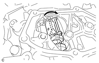
Move the inner select lever as shown in the illustration.
-
*a
Shift and Select Lever Shaft Head
*b
Shift Actuator Plate
*c
Select Actuator Plate
*d
Inner Select Lever
Install the shift and select actuator and wire harness clamp bracket to the front transaxle case with the 6 bolts.
18 N*m
184 kgf*cm
13 ft.*lbf
Note:Securely engage the shift actuator plate to the shift and select lever shaft head.
Securely engage the select actuator plate to the inner select lever.
-
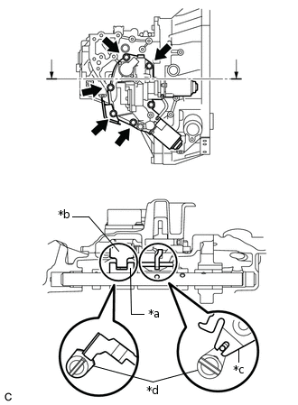
When reusing the shift and select actuator:
-

*a
Shift and Select Lever Shaft Head
*b
Shift Actuator Plate
*c
Select Actuator Plate
*d
Inner Select Lever
Install the shift and select actuator to the front transaxle case with the 6 bolts.
18 N*m
184 kgf*cm
13 ft.*lbf
Note:Securely engage the shift actuator plate to the shift and select lever shaft head.
Securely engage the select actuator plate to the inner select lever.
-
Install the wire harness clamp bracket to the shift and select actuator with the bolt.
12.5 N*m
127 kgf*cm
9 ft.*lbf
Install the wire harness clamp bracket to the shift and select actuator with the bolt.
8.0 N*m
82 kgf*cm
71 in.*lbf
CONNECT WIRE HARNESS
Connect the connector and 3 wire harness clamps.
Connect the 6 connectors.
Connect the 5 wire harness clamps.
INSTALL NO. 1 AIR TUBE
-
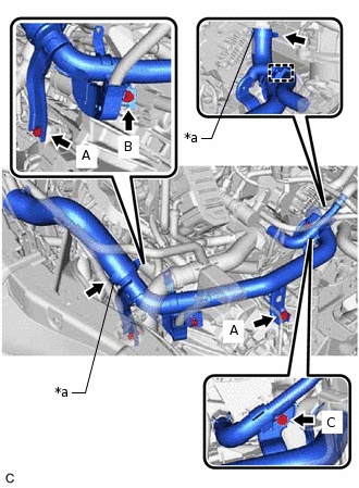
*a
Hose Clamp
Install the No. 1 air tube and tighten the 2 hose clamps.
6.5 N*m
66 kgf*cm
58 in.*lbf
Note:One minute after tightening the hose clamps, check that residual torque is 3.2 N*m (33 kgf*cm, 28 in.*lbf) or more.
Install the 4 bolts.
Bolt A
20 N*m
204 kgf*cm
15 ft.*lbf
Bolt B
12.5 N*m
127 kgf*cm
9 ft.*lbf
Bolt C
9.8 N*m
100 kgf*cm
87 in.*lbf
Connect the wire harness clamp.
-
INSTALL AIR CLEANER BRACKET
INSTALL FUEL FILTER SUPPORT
CONNECT ENGINE WIRE
INSTALL FUEL FILTER ASSEMBLY
INSTALL BATTERY
CONNECT CABLE TO NEGATIVE BATTERY TERMINAL
Note:When disconnecting the cable, some systems need to be initialized after the cable is reconnected.
PERFORM INITIALIZATION OF MULTI-MODE MANUAL TRANSAXLE SYSTEM
PERFORM LEARNING OF MULTI-MODE MANUAL TRANSAXLE SYSTEM
PERFORM SYNCHRONIZATION POSITION CALIBRATION