AIRBAG SYSTEM, Diagnostic DTC:B1651/33
| DTC Code | DTC Name |
|---|---|
| B1651/33 | Manual Cut off Switch Trouble |
DESCRIPTION
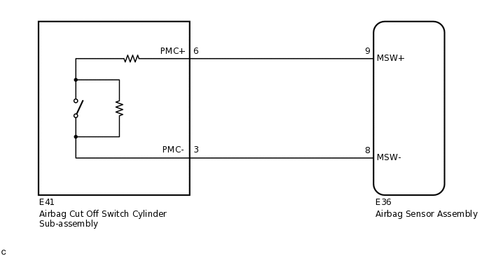
The airbag cut off switch circuit consists of the airbag sensor assembly and airbag cut off switch cylinder sub-assembly.
The instrument panel passenger airbag assembly can be optionally deactivated via this circuit by turning the airbag cut off switch cylinder sub-assembly to the OFF position.
If the instrument panel passenger airbag assembly is deactivated, the passenger airbag ON/OFF indicator ("OFF") comes on to inform the driver.
DTC B1651/33 is stored when a malfunction is detected in the airbag cut off switch circuit.
DTC No. |
Detection Item |
DTC Detection Condition |
Trouble Area |
Test Mode / Check Mode |
|---|---|---|---|---|
B1651/33 |
Manual Cut off Switch Trouble |
|
|
Does not apply to test/check mode |
WIRING DIAGRAM
CAUTION / NOTICE / HINT
After turning the ignition switch off, waiting time may be required before disconnecting the cable from the negative (-) battery terminal. Therefore, make sure to read the disconnecting the cable from the negative (-) battery terminal notices before proceeding with work.
PROCEDURE
CHECK CONNECTORS
Turn the ignition switch off.
Disconnect the cable from the negative (-) battery terminal.
CAUTION:Wait at least 90 seconds after disconnecting the cable from the negative (-) battery terminal to disable the SRS system.
Check that the connectors are properly connected to the airbag sensor assembly and airbag cut off switch cylinder sub-assembly.
OK
The connectors are properly connected.
Tip:If the connectors are not properly connected, reconnect the connectors and proceed to the next inspection.
Disconnect the connectors from the airbag sensor assembly and airbag cut off switch cylinder sub-assembly.
Check that the terminals of the connectors are not damaged.
OK
The terminals are not deformed or damaged.
Result
Proceed to
OK
NG
NG REPLACE INSTRUMENT PANEL WIRE
CHECK INSTRUMENT PANEL WIRE (OPEN)
-
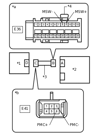
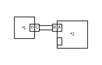
*1
Airbag Cut Off Switch Cylinder Sub-assembly
*2
Airbag Sensor Assembly
*3
Instrument Panel Wire
*4
Service Wire
*a
Front view of wire harness connector
(to Airbag Sensor Assembly)
*b
Front view of wire harness connector
(to Airbag Cut Off Switch Cylinder Sub-assembly)
Using a service wire, connect terminals 9 (MSW+) and 8 (MSW-) of connector B.
Note:Do not forcibly insert the service wire into the terminals of the connector when connecting the wire.
Measure the resistance according to the value(s) in the table below.
Standard Resistance
Tester Connection
Condition
Specified Condition
E41-6 (PMC+) - E41-3 (PMC-)
Always
Below 1 Ω
Disconnect the service wire from connector B.
Result
Proceed to
OK
NG
NG REPLACE INSTRUMENT PANEL WIRE
-
CHECK INSTRUMENT PANEL WIRE (SHORT)
-
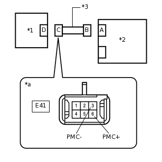
*1
Airbag Cut Off Switch Cylinder Sub-assembly
*2
Airbag Sensor Assembly
*3
Instrument Panel Wire
*a
Front view of wire harness connector
(to Airbag Cut Off Switch Cylinder Sub-assembly)
Measure the resistance according to the value(s) in the table below.
Standard Resistance
Tester Connection
Condition
Specified Condition
E41-6 (PMC+) - E41-3 (PMC-)
Always
1 MΩ or higher
Result
Proceed to
OK
NG
NG REPLACE INSTRUMENT PANEL WIRE
-
CHECK INSTRUMENT PANEL WIRE (SHORT TO B+)
-
*1
Airbag Cut Off Switch Cylinder Sub-assembly
*2
Airbag Sensor Assembly
*3
Instrument Panel Wire
*a
Front view of wire harness connector
(to Airbag Cut Off Switch Cylinder Sub-assembly)
Connect the cable to the negative (-) battery terminal.
Turn the ignition switch to ON.
Measure the voltage according to the value(s) in the table below.
Standard Voltage
Tester Connection
Condition
Specified Condition
E41-6 (PMC+) - Body ground
Ignition switch ON
Below 1 V
E41-3 (PMC-) - Body ground
Ignition switch ON
Below 1 V
Turn the ignition switch off.
Disconnect the cable from the negative (-) battery terminal.
CAUTION:Wait at least 90 seconds after disconnecting the cable from the negative (-) battery terminal to disable the SRS system.
Result
Proceed to
OK
NG
NG REPLACE INSTRUMENT PANEL WIRE
-
CHECK INSTRUMENT PANEL WIRE (SHORT TO GROUND)
-
*1
Airbag Cut Off Switch Cylinder Sub-assembly
*2
Airbag Sensor Assembly
*3
Instrument Panel Wire
*a
Front view of wire harness connector
(to Airbag Cut Off Switch Cylinder Sub-assembly)
Measure the resistance according to the value(s) in the table below.
Standard Resistance
Tester Connection
Condition
Specified Condition
E41-6 (PMC+) - Body ground
Always
1 MΩ or higher
E41-3 (PMC-) - Body ground
Always
1 MΩ or higher
Result
Proceed to
OK
NG
NG REPLACE INSTRUMENT PANEL WIRE
-
CHECK AIRBAG CUT OFF SWITCH CYLINDER SUB-ASSEMBLY
-
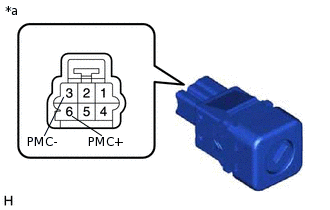
*a
Component without harness connected
(Airbag Cut Off Switch Cylinder Sub-assembly)
Measure the resistance according to the value(s) in the table below.
Standard Resistance
Tester Connection
Condition
Specified Condition
6 (PMC+) - 3 (PMC-)
Cut off switch ON
360 to 440 Ω
6 (PMC+) - 3 (PMC-)
Cut off switch OFF
90 to 110 Ω
Result
Proceed to
OK
NG
-
CHECK DTC
-
*1
Airbag Cut Off Switch Cylinder Sub-assembly
*2
Airbag Sensor Assembly
Connect the connectors to the airbag sensor assembly and airbag cut off switch cylinder sub-assembly.
Connect the cable to the negative (-) battery terminal.
Clear the DTCs stored in memory.
Body Electrical > SRS Airbag > Clear DTCs
Turn the ignition switch off.
Turn the ignition switch to ON, and wait for at least 60 seconds.
Check for DTCs.
Body Electrical > SRS Airbag > Trouble Codes
OK
DTC B1651/33 is not output.
Tip:Codes other than DTC B1651/33 may be output at this time, but they are not related to this check.
Result
Proceed to
OK
NG
-