CLUTCH UNIT(for C553A) INSTALLATION
PROCEDURE
INSTALL CLUTCH DISC ASSEMBLY
-

Flywheel Sub-assembly Side
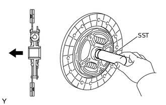
Insert SST into the clutch disc assembly, and then insert them both into the flywheel sub-assembly.
09301-00131
Note:Do not insert the clutch disc assembly in the wrong direction.
-
INSTALL CLUTCH COVER ASSEMBLY
-
*a
Temporarily
*b
Matchmark
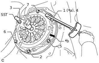
Align the matchmark on the clutch cover assembly with the one on the flywheel sub-assembly.
Following the procedure shown in the illustration, tighten the 6 bolts in order, starting with the bolt located near the knock pin at the top.
09301-00131
19.1 N*m
195 kgf*cm
14 ft.*lbf
Tip:Following the order in the illustration, tighten the bolts evenly one at a time.
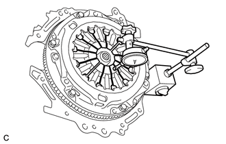
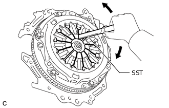
Move SST up and down, right and left lightly after checking that the clutch disc assembly is in the center, and tighten the bolts.
-
INSPECT AND ADJUST CLUTCH COVER ASSEMBLY
-
Using a dial indicator with a roller instrument, check the diaphragm spring tip alignment.
Maximum Non-alignment
0.5 mm (0.0197 in.)
-
If the alignment is not as specified, using SST, adjust the diaphragm spring tip alignment.
09333-00013
-
INSTALL NO. 1 CLUTCH HOUSING COVER
Install the No. 1 clutch housing cover to the multi-mode manual transaxle assembly.
INSTALL CLUTCH RELEASE FORK LEVER SHAFT OIL SEAL
-
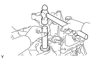
Using SST and a hammer, tap in a new clutch release fork lever shaft oil seal until its surface is flush with the multi-mode manual transaxle assembly.
09950-60010
09951-00290
09950-70010
09951-07150
-
INSTALL CLUTCH RELEASE FORK LEVER
-
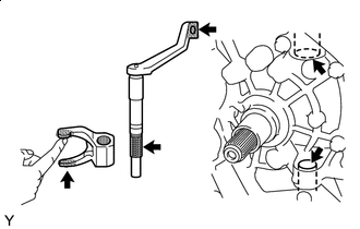
Release Hub Grease
Apply release hub grease to the contact surfaces of the clutch release bearing assembly and the clutch release fork, the rotating and sliding parts of the clutch release fork lever, and the spline coupling.
Grease
Toyota Genuine Release Hub Grease or equivalent
Note:Wipe off any grease extending beyond the contact surfaces of the clutch release fork lever.
Install the clutch release bearing assembly to the clutch release fork.
Install the clutch release fork with clutch release bearing assembly to the multi-mode manual transaxle assembly together with the clutch release fork lever.
Install the clip to the clutch release bearing assembly.
-
Install a new E-ring to the clutch release fork lever.
-
INSTALL CLUTCH RELEASE BEARING ASSEMBLY
Install the clutch release bearing assembly to the clutch release fork with the clip.
-
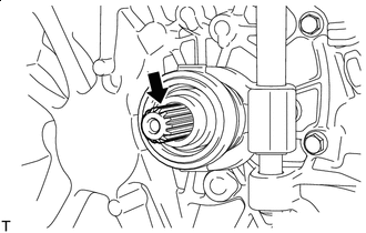
Clutch Spline Grease
Apply clutch spline grease to the input shaft spline.
Grease
Toyota Genuine Clutch Spline Grease or Equivalent
INSTALL SHIFT STROKE SENSOR
Apply MP grease to a new O-ring, and install it to the shift stroke sensor.
-
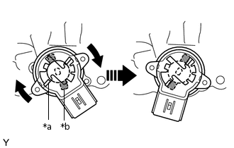
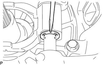
*a
Sensor Arm (Actuator Side)
*b
Sensor Arm (Sensor Side)
Set the shift stroke sensor so that the sensor side and the actuator side sensor arms are in the positions shown in the illustration.
Turn the shift stroke sensor clockwise and secure it with the 2 screws.
2.0 N*m
20 kgf*cm
18 in.*lbf
INSTALL MULTI-MODE MANUAL TRANSAXLE ASSEMBLY