STEERING PAD SWITCH INSPECTION
PROCEDURE
INSPECT STEERING PAD SWITCH ASSEMBLY
Inspect the pad switch.
Measure the resistance according to the value(s) in the table below.
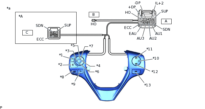
*A
w/ Shift Paddle Switch
-
-
*1
Volume+ Switch
*2
Volume- Switch
*3
Left Switch
*4
Right Switch
*5
Up Switch
*6
Down Switch
*7
ENTER Switch
*8
MODE Switch
*9
Back Switch
*10
w/ Voice Switch
*11
Off Hook Switch
*12
On Hook Switch
*13
DISP Switch
-
-
*a
Component without harness connected
(Steering Pad Switch Assembly)
-
-
Standard Resistance
Tester Connection
Switch Condition
Specified Condition
A11 (AU1) - A8 (EAU)
No switch is pushed
95 to 105 kΩ
Volume+ is pushed
950 to 1050 Ω
Volume- is pushed
2954 to 3265 Ω
Up switch is pushed
Below 2.5 Ω
Down switch is pushed
312 to 345 Ω
A9 (AU3) - A8 (EAU)
No switch is pushed
95 to 105 kΩ
Left switch is pushed
2954 to 3265 Ω
Right switch is pushed
950 to 1050 Ω
ENTER Switch is pushed
Below 2.5 Ω
Back Switch is pushed
312 to 345 Ω
A10 (AU2) - A8 (EAU)
No switch is pushed
95 to 105 kΩ
MODE switch is pushed
Below 2.5 Ω
On Hook switch is pushed
312 to 345 Ω
Off Hook switch is pushed
950 to 1050 Ω
Voice switch is pushed
2954 to 3265 Ω
A2 (+DP) - A3 (-DP)
DISP switch is pushed
Below 2.5 Ω
A1 (HO) - B (HO)
Always
Below 2.5 Ω
A6 (SUP) - C2 (SUP)
Always
Below 2.5 Ω
A12 (SDN) - C3 (SDN)
Always
Below 2.5 Ω
A7 (ECC) - C7 (ECC)
Always
Below 2.5 Ω
If the result is not as specified, replace the steering pad switch assembly.
Connect the battery positive (+) lead to terminal A5 (IL+2) and the negative (-) lead to terminal A8 (EAU) of the steering pad switch assembly connector.
Check that the switch illumination comes on.
OK
Steering pad switch illumination comes on.
If the result is not as specified, replace the steering pad switch assembly.
Inspect the pad switch.
Measure the resistance according to the value(s) in the table below.
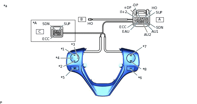
*A
w/ Shift Paddle Switch
-
-
*1
Volume+ Switch
*2
Volume- Switch
*3
Seek+ Switch
*4
Seek- Switch
*5
MODE Switch
*6
DISP Switch
*7
w/ Off Hook Switch
*8
w/ On Hook Switch
*a
Component without harness connected
(Steering Pad Switch Assembly)
-
-
Standard Resistance
Tester Connection
Switch Condition
Specified Condition
A11 (AU1) - A8 (EAU)
No switch is pushed
95 to 105 kΩ
Volume+ is pushed
950 to 1050 Ω
Volume- is pushed
2954 to 3265 Ω
Seek+ switch is pushed
Below 2.5 Ω
Seek- switch is pushed
312 to 345 Ω
A10 (AU2) - A8 (EAU)
No switch is pushed
95 to 105 kΩ
MODE switch is pushed
Below 2.5 Ω
On Hook switch is pushed
312 to 345 Ω
Off Hook switch is pushed
950 to 1050 Ω
A2 (+DP) - A3 (-DP)
DISP switch is pushed
Below 2.5 Ω
A5 (HO) - B (HO)
Always
Below 2.5 Ω
A6 (SUP) - C2 (SUP)
Always
Below 2.5 Ω
A12 (SDN) - C3 (SDN)
Always
Below 2.5 Ω
A7 (ECC) - C7 (ECC)
Always
Below 2.5 Ω
If the result is not as specified, replace the steering pad switch assembly.
Connect the battery positive (+) lead to terminal A1 (IL+2) and the negative (-) lead to terminal A8 (EAU) of the steering pad switch assembly connector.
Check that the switch illumination comes on.
OK
Steering pad switch illumination comes on.
If the result is not as specified, replace the steering pad switch assembly.