PRE-CRASH SAFETY SYSTEM, Diagnostic DTC:C1A4B
| DTC Code | DTC Name |
|---|---|
| C1A4B | Stop Light Relay Circuit |
DESCRIPTION
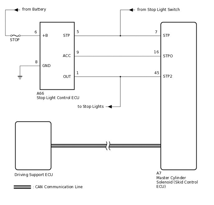
The skid control ECU outputs a stop light operation signal to the stop light control ECU. When the skid control ECU detects a malfunction in the stop light circuit, the driving support ECU outputs DTC C1A4B.
DTC No. |
Detection Item |
DTC Detection Condition |
Trouble Area |
DTC Output from |
|---|---|---|---|---|
C1A4B |
Stop Light Relay Circuit |
Either of the following conditions is met:
|
|
Driving Support ECU (Pre-Crash 2) |
WIRING DIAGRAM
CAUTION / NOTICE / HINT
When replacing the master cylinder solenoid, perform calibration Click here.
Inspect the fuses for circuits related to this system before performing the following inspection procedure.
This circuit uses CAN communication. Therefore, if there are any malfunctions in the communication circuit, one or more DTCs in the CAN communication system are output.
PROCEDURE
CHECK STOP LIGHT OPERATION
Check that the stop lights come on when the brake pedal is depressed and go off when the brake pedal is released.
OK
Condition
Illumination Condition
Brake pedal depressed
On
Brake pedal released
Off
Result
Proceed to
OK
NG
CHECK TERMINAL VOLTAGE AND RESISTANCE (+B, GND)
Disconnect the A66 stop light control ECU connector.
-
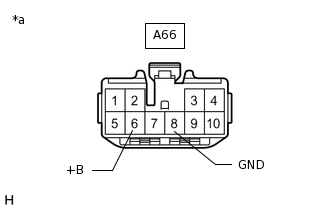
*a
Front view of wire harness connector
(to Stop Light Control ECU)
Measure the voltage according to the value(s) in the table below.
Standard Voltage
Tester Connection
Condition
Specified Condition
A66-6 (+B) - Body ground
Always
11 to 14 V
Measure the resistance according to the value(s) in the table below.
Standard Resistance
Tester Connection
Condition
Specified Condition
A66-8 (GND) - Body ground
Always
Below 1 Ω
Result
Proceed to
OK
NG
NG REPAIR OR REPLACE HARNESS OR CONNECTOR
CHECK TERMINAL VOLTAGE (STP)
Disconnect the A7 skid control ECU connector.
-
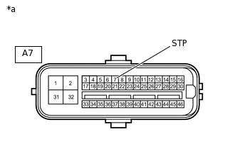
(to Skid Control ECU)
*a
Front view of wire harness connector
(to Skid Control ECU)
Measure the voltage according to the value(s) in the table below.
Standard Voltage
Tester Connection
Condition
Specified Condition
A7-7 (STP) - Body ground
Brake pedal depressed
11 to 14 V
Brake pedal released
Below 1.5 V
Result
Proceed to
OK
NG
NG REPAIR OR REPLACE HARNESS OR CONNECTOR
CHECK TERMINAL VOLTAGE (STP)
Disconnect the A66 stop light control ECU connector.
-
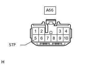
*a
Front view of wire harness connector
(to Stop Light Control ECU)
Measure the voltage according to the value(s) in the table below.
Standard Voltage
Tester Connection
Condition
Specified Condition
A66-5 (STP) - Body ground
Brake pedal depressed
11 to 14 V
Brake pedal released
Below 1.5 V
Result
Proceed to
OK
NG
NG REPAIR OR REPLACE HARNESS OR CONNECTOR
PERFORM ACTIVE TEST USING INTELLIGENT TESTER (STOP LIGHT RELAY)
Connect the intelligent tester to the DLC3.
Turn the engine switch on (IG).
Turn the intelligent tester on.
Enter the following menus: Chassis / ABS/VSC/TRC / Active Test.
Chassis > ABS/VSC/TRC > Active Test
Tester Display
Measurement Item
Control Range
Diagnostic Note
Stop Light Relay
STOP LP relay
Relay ON/OFF
Observe the stop lights (do not come on for 2 to 5 seconds).
Chassis > ABS/VSC/TRC > Active Test
Tester Display
Stop Light Relay
While performing the Active Test, check the illumination condition of the stop lights and "Stop Light Relay Output" in the Data List.
Result
Proceed to
Proceed to
When Active Test performed, Data List item changes between ON and OFF, but stop lights do not turn on
A
When Active Test performed, Data List item changes between ON and OFF and stop lights turn on and off
B
B CHECK HARNESS AND CONNECTOR (STOP LIGHT CONTROL ECU - SKID CONTROL ECU)Click here
CHECK HARNESS AND CONNECTOR (STOP LIGHT CONTROL ECU - SKID CONTROL ECU)
Disconnect the A66 stop light control ECU connector.
Disconnect the A7 skid control ECU connector.
Measure the resistance according to the value(s) in the table below.
Standard Resistance
Tester Connection
Condition
Specified Condition
A66-9 (ACC) - A7-16 (STPO)
Always
Below 1 Ω
A66-9 (ACC) - Body ground
Always
10 kΩ or higher
Result
Proceed to
OK
NG
NG REPAIR OR REPLACE HARNESS OR CONNECTOR
CHECK HARNESS AND CONNECTOR (STOP LIGHT CONTROL ECU - SKID CONTROL ECU)
Disconnect the A66 stop light control ECU connector.
Disconnect the A7 skid control ECU connector.
Measure the resistance according to the value(s) in the table below.
Standard Resistance
Tester Connection
Condition
Specified Condition
A66-1 (OUT) - A7-45 (STP2)
Always
Below 1 Ω
Result
Proceed to
OK
NG
NG REPAIR OR REPLACE HARNESS OR CONNECTOR
CHECK TERMINAL VOLTAGE (STP2)
Disconnect the A7 skid control ECU connector.
-
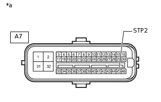
*a
Front view of wire harness connector
(to Skid Control ECU)
Measure the voltage according to the value(s) in the table below.
Standard Voltage
Tester Connection
Condition
Specified Condition
A7-45 (STP2) - Body ground
Brake pedal depressed
11 to 14 V
Brake pedal released
Below 1.5 V
Result
Proceed to
OK
NG
CHECK FOR DTC (PRE-CRASH SAFETY SYSTEM)
Turn the engine switch off and wait for at least 2 minutes.
Clear the DTCs .
Body Electrical > Pre-Crash > Clear DTCs
Make sure that the DTC detection conditions are met.
Tip:If the detection conditions are not met, the system cannot detect malfunctions.
Using the intelligent tester, perform the Active Test "Stop Light Relay" with the engine switch on (IG).
Check for DTCs .
Body Electrical > Pre-Crash > Trouble Codes
Note:When replacing the driving support ECU, always replace it with a new one and be sure to perform initialization (Click here). If an ECU which was installed to anothervehicle is used, the information stored in the ECU will not match the information from the vehicle, and as a result, a DTC may be stored.
OK
DTCs C1A4B are not output.
Result
Proceed to
OK
NG
OK END