REAR COMBINATION LIGHT ASSEMBLY ON-VEHICLE INSPECTION
PROCEDURE
INSPECT REAR COMBINATION LIGHT ASSEMBLY LH
-
*A
for RHD
*B
for LHD
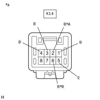
*a
Front view of wire harness connector
(to Rear Combination Light Assembly LH)
Disconnect the K14 rear combination light assembly LH connector.
Measure the voltage according to the value(s) in the table below.
Standard Voltage
Tester Connection
Condition
Specified Condition
K14-1 (B) - K14-5 (E)
Turn signal switch in neutral position
Below 1 V
Ignition switch ON, turn signal switch in left turn position
Alternating between 11 to 14 V and below 1 V
(60 to 120 times per minute)
K14-2 (B) - K14-5 (E)*1
Ignition switch ON, shift lever not in R
Below 1 V
Ignition switch ON, shift lever in R
11 to 14 V
K14-3 (B) - K14-5 (E)
Light control switch off
Below 1 V
Light control switch in tail position
11 to 14 V
K14-4 (B) - K14-5 (E)
Brake pedal released
Below 1 V
Brake pedal depressed
11 to 14 V
K14-6 (B) - K14-5 (E)*2
Light control switch in tail position, fog light switch not in rear position
Below 1 V
Light control switch in tail position, fog light switch in rear position
11 to 14 V
*1: for RHD
*2: for LHD
If the result is not as specified, repair or replace the wire harness or connector.
-
INSPECT REAR COMBINATION LIGHT ASSEMBLY RH
-
*A
for LHD
*B
for RHD
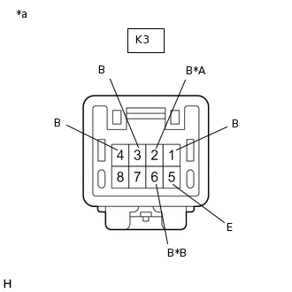
*a
Front view of wire harness connector
(to Rear Combination Light Assembly RH)
Disconnect the K3 rear combination light assembly RH connector.
Measure the voltage according to the value(s) in the table below.
Standard Voltage
Tester Connection
Condition
Specified Condition
K3-1 (B) - K3-5 (E)
Turn signal switch in neutral position
Below 1 V
Ignition switch ON, turn signal switch in right turn position
Alternating between 11 to 14 V and below 1 V
(60 to 120 times per minute)
K3-2 (B) - K3-5 (E)*1
Ignition switch ON, shift lever not in R
Below 1 V
Ignition switch ON, shift lever in R
11 to 14 V
K3-3 (B) - K3-5 (E)
Light control switch off
Below 1 V
Light control switch in tail position
11 to 14 V
K3-4 (B) - K3-5 (E)
Brake pedal released
Below 1 V
Brake pedal depressed
11 to 14 V
K3-6 (B) - K3-5 (E)*2
Light control switch in tail position, fog light switch not in rear position
Below 1 V
Light control switch in tail position, fog light switch in rear position
11 to 14 V
*1: for LHD
*2: for RHD
If the result is not as specified, repair or replace the wire harness or connector.
-