SFI SYSTEM(w/ EGR System) Fuel Pump Control Circuit
| DTC Code | DTC Name |
|---|---|
| Fuel Pump Control Circuit |
DESCRIPTION
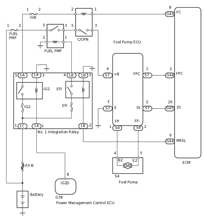
The fuel pump circuit consists of the ECM, fuel pump and fuel pump ECU (which operates the fuel pump). Based on the engine output, the ECM determines the fuel pump speed. The speed is then converted to a duty signal and sent to the fuel pump ECU. Based on the signal sent from the ECM, the fuel pump ECU adjusts the fuel pump operation speed among 3 settings.
WIRING DIAGRAM
CAUTION / NOTICE / HINT
Inspect the fuses for circuits related to this system before performing the following inspection procedure.
This troubleshooting procedure is based on the premise that the engine can be started. If the engine cannot be started, proceed to Problem Symptoms Table (Click here).
PROCEDURE
PERFORM ACTIVE TEST USING INTELLIGENT TESTER
Connect the intelligent tester to the DLC3.
Turn the engine switch on (IG).
Turn the tester on.
Enter the following menus: Powertrain / Engine and ECT / Active Test / Control the Fuel Pump / Speed.
Powertrain > Engine and ECT > Active Test
Tester Display
Control the Fuel Pump / Speed
Check whether operating sounds can be heard while operating the fuel pump using the intelligent tester.
OK
Operating sounds can be heard from fuel pump.
Result
Result
OK
NG
INSPECT CIRCUIT OPENING RELAY (C/OPN)
Inspect the circuit opening relay (C/OPN).
Result
Result
OK
NG
NG REPLACE CIRCUIT OPENING RELAY (C/OPN)
INSPECT CIRCUIT OPENING RELAY (C/OPN) (POWER SOURCE VOLTAGE)
Remove the circuit opening relay (C/OPN) from the engine room relay block.
Turn the engine switch on (IG).
-
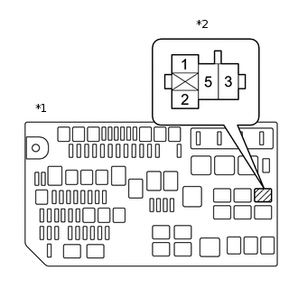
*1
Engine Room Relay Block
*2
Circuit Opening Relay (C/OPN)
Measure the voltage according to the value(s) in the table below.
Standard Voltage
Tester Connection
Switch Condition
Specified Condition
C/OPN relay (2) - Body ground
Engine switch on (IG)
11 to 14 V
C/OPN relay (5) - Body ground
Engine switch on (IG)
11 to 14 V
Result
Result
OK
NG
NG CHECK HARNESS AND CONNECTOR (CIRCUIT OPENING RELAY (C/OPN) - FUEL PUMP RELAY (F/PMP) AND NO. 1 INTEGRATION RELAY)Click here
CHECK HARNESS AND CONNECTOR (CIRCUIT OPENING RELAY (C/OPN) - ECM AND FUEL PUMP ECU)
Remove the circuit opening relay (C/OPN) from the engine room relay block.
Disconnect the ECM connector.
Disconnect the fuel pump ECU connector.
Measure the resistance according to the value(s) in the table below.
Standard Resistance
Tester Connection
Condition
Specified Condition
C/OPN relay (1) - G45-8 (FC)
Always
Below 1 Ω
C/OPN relay (3) - S7-4 (+B)
Always
Below 1 Ω
C/OPN relay (1) or G45-8 (FC) - Body ground
Always
10 kΩ or higher
C/OPN relay (3) or S7-4 (+B) - Body ground
Always
10 kΩ or higher
Result
Result
OK
NG
NG REPAIR OR REPLACE HARNESS OR CONNECTOR
CHECK HARNESS AND CONNECTOR (FUEL PUMP - FUEL PUMP ECU)
Disconnect the fuel pump connector.
Disconnect the fuel pump ECU connector.
Measure the resistance according to the value(s) in the table below.
Standard Resistance
Tester Connection
Condition
Specified Condition
S4-4 (B2) - S8-1 (FP)
Always
Below 1 Ω
S4-5 (E2) - S8-2 (FP-)
Always
Below 1 Ω
S4-4 (B2) or S8-1 (FP) - Body ground
Always
10 kΩ or higher
S4-5 (E2) or S8-2 (FP-) - Body ground
Always
10 kΩ or higher
Result
Result
OK
NG
NG REPAIR OR REPLACE HARNESS OR CONNECTOR
INSPECT FUEL PUMP
Inspect the fuel pump.
Result
Result
OK
NG
CHECK HARNESS AND CONNECTOR (FUEL PUMP ECU - ECM AND BODY GROUND)
Disconnect the fuel pump ECU connector.
Disconnect the ECU connector.
Measure the resistance according to the value(s) in the table below.
Standard Resistance
Tester Connection
Condition
Specified Condition
S7-1 (FPC) - G44-3 (FPC)
Always
Below 1 Ω
S7-2 (DI) - G45-26 (DI)
Always
Below 1 Ω
S7-3 (E) - Body ground
Always
Below 1 Ω
S7-1 (FPC) or G44-3 (FPC) - Body ground
Always
10 kΩ or higher
S7-2 (DI) or G45-26 (DI) - Body ground
Always
10 kΩ or higher
Result
Result
OK
NG
NG REPAIR OR REPLACE HARNESS OR CONNECTOR
REPLACE FUEL PUMP ECU
Replace the fuel pump ECU.
Result
Result
NEXT
CONFIRM WHETHER MALFUNCTION HAS BEEN SUCCESSFULLY REPAIRED
Check the fuel pump operation.
OK
Malfunction has been repaired successfully.
Result
Result
OK
NG
OK END
CHECK HARNESS AND CONNECTOR (CIRCUIT OPENING RELAY (C/OPN) - FUEL PUMP RELAY (F/PMP) AND NO. 1 INTEGRATION RELAY)
Remove the circuit opening relay (C/OPN) from the engine room relay block.
Remove the fuel pump relay (F/PMP) from the engine room relay block.
Remove the No. 1 integration relay from the engine room relay block.
Measure the resistance according to the value(s) in the table below.
Standard Resistance
Tester Connection
Condition
Specified Condition
C/OPN relay (2) - 1A-5
Always
Below 1 Ω
C/OPN relay (5) - F/PMP relay (3)
Always
Below 1 Ω
C/OPN relay (2) or 1A-5 - Body ground
Always
10 kΩ or higher
C/OPN relay (5) or F/PMP relay (3) - Body ground
Always
10 kΩ or higher
Result
Result
OK
NG
NG REPAIR OR REPLACE HARNESS OR CONNECTOR
INSPECT FUEL PUMP RELAY (F/PMP)
Inspect the fuel pump relay (F/PMP)
Result
Result
OK
NG
NG REPLACE FUEL PUMP RELAY (F/PMP)
CHECK HARNESS AND CONNECTOR (FUEL PUMP RELAY (F/PMP) - NO. 1 INTEGRATION RELAY, BATTERY AND BODY GROUND)
Remove the fuel pump relay (F/PMP) from the engine room relay block.
Remove the No. 1 integration relay from the engine room relay block.
Disconnect the No. 1 integration relay connector.
Disconnect the cable from the battery positive (+) terminal.
Measure the resistance according to the value(s) in the table below.
Standard Resistance
Tester Connection
Condition
Specified Condition
F/PMP relay (1) - 1B-4
Always
Below 1 Ω
F/PMP relay (5) - Positive (+) battery cable
Always
Below 1 Ω
F/PMP relay (2) - Body ground
Always
Below 1 Ω
F/PMP relay (1) or 1B-4 - Body ground
Always
10 kΩ or higher
F/PMP relay (5) or Positive (+) battery cable - Body ground
Always
10 kΩ or higher
Result
Result
OK
NG
NG REPAIR OR REPLACE HARNESS OR CONNECTOR