LIGHTING SYSTEM Stop Light Circuit
DESCRIPTION
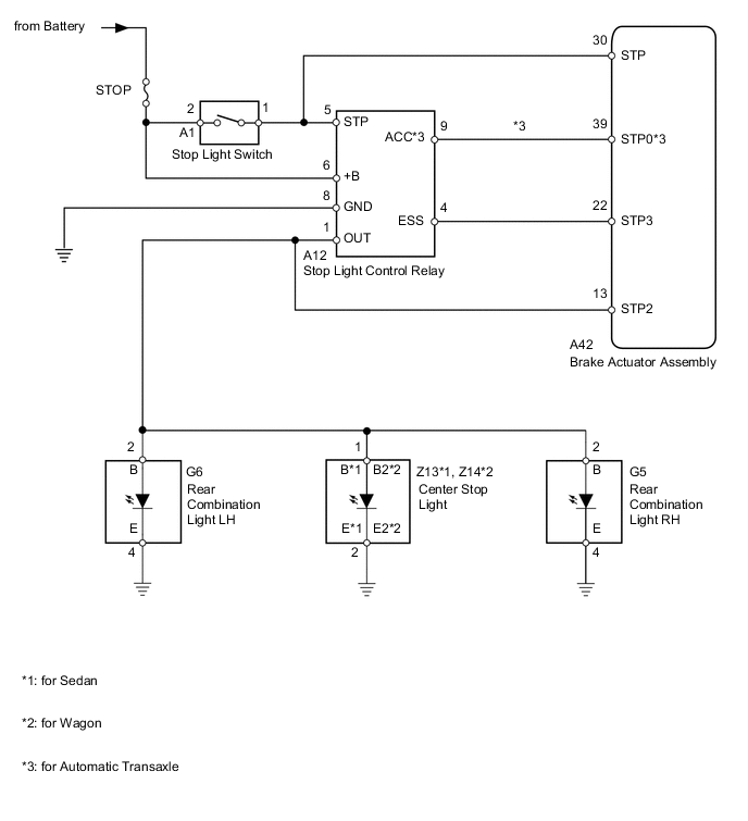
When the stop light switch is turned on, current flows to the stop lights to illuminate them. In emergency braking, the brake control system blinks all stop lights to alert a following driver, and reduces the possibility of rear-end collision.
WIRING DIAGRAM
CAUTION / NOTICE / HINT
Tech Tips
Inspect the fuses and bulbs for circuits related to this system before performing the following inspection procedure.
PROCEDURE
-
CHECK FOR DTC (BRAKE CONTROL SYSTEM)
-
Clear the DTCs Click here.
-
Check for DTCs Click here.
OK DTCs output does not occur.
NG 
GO TO BRAKE CONTROL SYSTEM Click here
OK 
-
-
INSPECT STOP LIGHT SWITCH ASSEMBLY
-
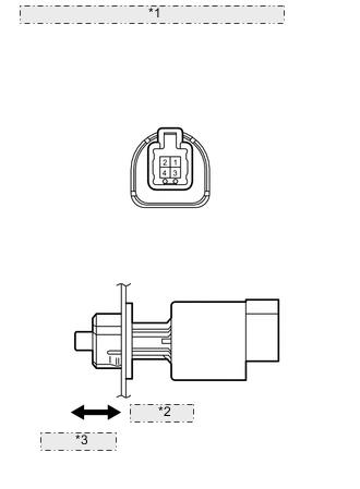
*1 Component without harness connected: (Stop Light Switch) *2 Pin pushed *3 Pin released Remove the stop light switch Click here.
-
Measure the resistance according to the value(s) in the table below.
Standard Resistance Tester Connection Switch Condition Specified Condition 1-2 Switch pin pushed Below 1 Ω 1-2 Switch pin released 10 kΩ or higher
NG
REPLACE STOP LIGHT SWITCH ASSEMBLY Click here
OK
-
-
CHECK HARNESS AND CONNECTOR (STOP LIGHT SWITCH - BATTERY)
-
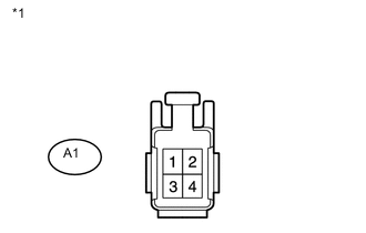
Text in Illustration *1 Front view of wire harness connector
(to Stop Light Switch)
Disconnect the A1 stop light switch connector.
-
Measure the voltage according to the value(s) in the table below.
Standard Voltage Tester Connection Condition Specified Condition A1-2 - Body ground Always 11 to 14 V
NG
REPAIR OR REPLACE HARNESS OR CONNECTOR
OK
-
-
CHECK HARNESS AND CONNECTOR (STOP LIGHT CONTROL RELAY - BATTERY)
-
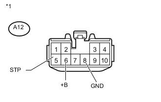
Text in Illustration *1 Front view of wire harness connector
(to Stop Light Control Relay)
Disconnect the A12 stop light control relay connector.
-
Measure the voltage according to the value(s) in the table below.
Standard Voltage Tester Connection Condition Specified Condition A12-5 (STP) - Body ground Brake pedal depressed 11 to 14 V A12-5 (STP) - Body ground Brake pedal released Below 1 V A12-6 (+B) - Body ground Always 11 to 14 V -
Measure the resistance according to the value(s) in the table below.
Standard Resistance Tester Connection Condition Specified Condition A12-8 (GND) - Body ground Always Below 1 Ω
NG
REPAIR OR REPLACE HARNESS OR CONNECTOR
OK
-
-
CHECK STOP LIGHT OPERATION
-
Check the stop light operation.
Result Result Proceed to All stop lights do not blink A Stop lights illuminate B Stop lights blink C
B 
CHECK HARNESS AND CONNECTOR (STOP LIGHT CONTROL RELAY - REAR COMBINATION LIGHT AND CENTER STOP LIGHT) Click here
C
CHECK STOP LIGHT Click here
A
-
-
CHECK HARNESS AND CONNECTOR (STOP LIGHT CONTROL RELAY - REAR COMBINATION LIGHT AND CENTER STOP LIGHT)
-
Disconnect the A12 stop light control relay connector.
-
Rear Combination Light:
-
Disconnect the rear G6 or G5 combination light connector.
-
Measure the resistance according to the value(s) in the table below.
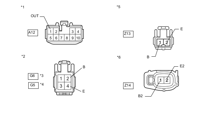
Standard Resistance for LH Tester Connection Condition Specified Condition A12-1 (OUT) - G6-2 (B) Always Below 1 Ω G6-4 (E) - Body ground G6-2 (B) - Body ground Always 10 kΩ or higher for RH Tester Connection Condition Specified Condition A12-1 (OUT) - G5-2 (B) Always Below 1 Ω G5-4 (E) - Body ground G5-2 (B) - Body ground Always 10 kΩ or higher
-
-
Center Stop Light:
-
Disconnect the Z13 or Z14 center stop light connector.
-
Measure the resistance according to the value(s) in the table below.
Standard Resistance for Sedan Tester Connection Condition Specified Condition A12-1 (OUT) - Z13-1 (B) Always Below 1 Ω Z13-2 (E) - Body ground Z13-1 (B) - Body ground Always 10 kΩ or higher for Wagon Tester Connection Condition Specified Condition A12-1 (OUT) - Z14-1 (B2) Always Below 1 Ω Z14-2 (E2) - Body ground Z14-1 (B2) - Body ground Always 10 kΩ or higher
Text in Illustration *1 Front view of wire harness connector
(to Stop Light Control Relay)
*2 Front view of wire harness connector
(to Rear Combination Light)
*3 for LH *4 for RH *5 Front view of wire harness connector
(to Center Stop Light [for Sedan])
*6 Front view of wire harness connector
(to Center Stop Light [for Wagon])
Result Result Proceed to OK (for LHD) A OK (for RHD) B NG C -
A
REPLACE STOP LIGHT CONTROL RELAY ASSEMBLY Click here
B
REPLACE STOP LIGHT CONTROL RELAY ASSEMBLY Click here
C
REPAIR OR REPLACE HARNESS OR CONNECTOR
-
-
CHECK HARNESS AND CONNECTOR (STOP LIGHT CONTROL RELAY - REAR COMBINATION LIGHT AND CENTER STOP LIGHT)
-
Disconnect the A12 stop light control relay connector.
-
Disconnect the G6 or G5 rear combination light connectors.
-
Disconnect the Z13 or Z14 center stop light connector.
-
Measure the voltage according to the value(s) in the table below.
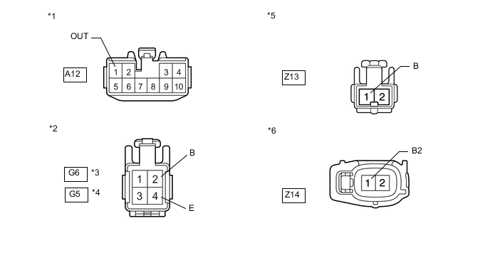
Standard Voltage for Sedan Tester Connection Condition Specified Condition A12-1 (OUT) - Body ground Always Below 1 V Z13-1 (B) - Body ground Always Below 1 V G6-2 (B) - Body ground Always Below 1 V G5-2 (B) - Body ground Always Below 1 V for Wagon Tester Connection Condition Specified Condition A12-1 (OUT) - Body ground Always Below 1 V Z14-1 (B2) - Body ground Always Below 1 V G6-2 (B) - Body ground Always Below 1 V G5-2 (B) - Body ground Always Below 1 V Text in Illustration *1 Front view of wire harness connector
(to Stop Light Control Relay)
*2 Front view of wire harness connector
(to Rear Combination Light)
*3 for LH *4 for RH *5 Front view of wire harness connector
(to Center Stop Light [for Sedan])
*6 Front view of wire harness connector
(to Center Stop Light [for Wagon])
Result Result Proceed to OK (for LHD) A OK (for RHD) B NG C
A
REPLACE STOP LIGHT CONTROL RELAY ASSEMBLY Click here
B
REPLACE STOP LIGHT CONTROL RELAY ASSEMBLY Click here
C
REPAIR OR REPLACE HARNESS OR CONNECTOR
-
-
CHECK STOP LIGHT
-
With the skid control ECU connector disconnected, check the illumination of the stop lights when depressing the brake pedal.
OK Stop lights operate normally when the brake pedal is depressed. Result Result Proceed to OK A NG (for LHD) B NG (for RHD) C
A
REPLACE BRAKE ACTUATOR ASSEMBLY Click here
B
REPLACE STOP LIGHT CONTROL RELAY ASSEMBLY Click here
C
REPLACE STOP LIGHT CONTROL RELAY ASSEMBLY Click here
-