FUEL FILTER REPLACEMENT

Info Added 2018-01-24 ![]()
CAUTION / NOTICE / HINT
Note
When working on the fuel circuit, protect the generator assembly against dirt contamination.
Cover the generator assembly with suitable materials.
Failure to comply with this procedure may result in a generator assembly malfunction.
PROCEDURE
-
REMOVE AIR CLEANER CAP SUB-ASSEMBLY WITH AIR CLEANER HOSE ASSEMBLY
-
REMOVE AIR CLEANER FILTER ELEMENT SUB-ASSEMBLY
-
REMOVE AIR CLEANER CASE SUB-ASSEMBLY
-
REMOVE FUEL FILTER ASSEMBLY (for Type A)
-
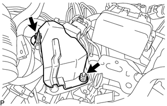
Remove the 2 nuts and No. 1 fuel filter protector.
-
Remove the No. 2 fuel pipe clamp from the No. 1 fuel hose.
-
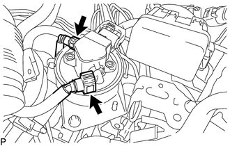
Disconnect the No. 1 fuel hose and No. 3 fuel hose from the fuel filter assembly.
-
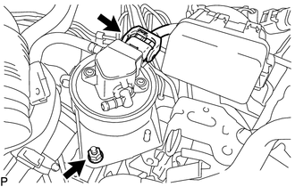
Disconnect the connector from the fuel filter assembly.
-
Remove nut and fuel filter assembly from the fuel filter support.
-
Remove the bolt and fuel filter cover from the fuel filter assembly.
-
-
REMOVE FUEL FILTER ASSEMBLY (for Type B)
-
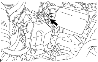
Disconnect the connector.
-
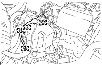
Detach the 4 clamps.
-
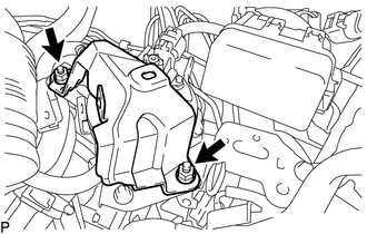
Remove the 2 nuts and No. 1 fuel filter protector.
-
Remove the No. 2 fuel pipe clamp from the No. 1 fuel hose.
-
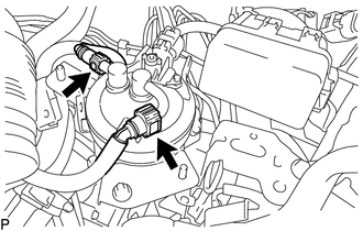
Disconnect the No. 1 fuel hose and No. 3 fuel hose from the fuel filter assembly.
-

Disconnect the connector from the fuel filter assembly.
-
Remove nut and fuel filter assembly from the fuel filter support.
-
Remove the bolt and fuel filter cover from the fuel filter assembly.
-
-
DRAIN FUEL
-
for Type A:
-
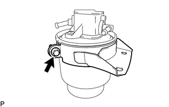
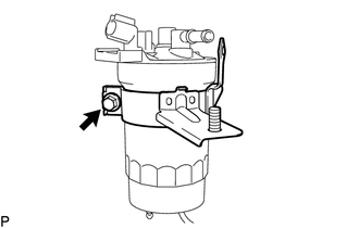
Loosen the drain cock and drain the fuel from the fuel filter assembly.
-
-
for Type B:
-
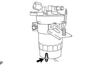
Loosen the drain cock and drain the fuel from the fuel filter assembly.
-
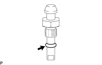
Remove the O-ring from the drain cock.
-
Tighten the drain cock.
- Torque:
- 3.1 N*m { 32 kgf*cm, 27 in.*lbf }
-
-
-
REMOVE FUEL FILTER ELEMENT ASSEMBLY (for Type B)
-
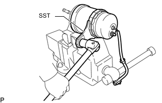
Using SST, remove the fuel filter case.
- SST
- 09228-64010
-
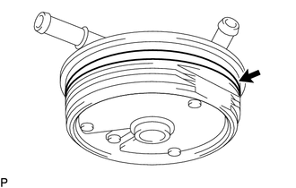
Remove the O-ring from the fuel filter cap.
-
Remove the fuel filter element assembly from the fuel filter case.
-
-
INSTALL FUEL FILTER ELEMENT ASSEMBLY (for Type B)
-
Check and clean the installation surface of the fuel filter case and fuel filter cap.
-
Apply fuel to the O-ring of a new fuel filter cap.
-
Install a new fuel filter element assembly to the fuel filter case.
-
Using SST, install the fuel filter case.
- SST
- 09228-64010
-
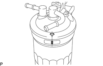
Align the mark on the fuel filter cap and fuel filter case.
-
-
INSTALL FUEL FILTER ASSEMBLY (for Type B)
-
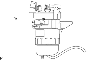
*a Protrusion Press the protrusion of the fuel filter cover against the fuel filter case.
-
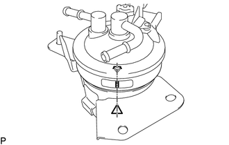
Align the mark on the fuel filter cap, fuel filter cover and the fuel filter case.
-
Install the fuel filter cover to the fuel filter assembly with the bolt.
- Torque:
- 12.5 N*m { 127 kgf*cm, 9 ft.*lbf }
-
Install the fuel filter assembly to the fuel filter support with the nut.
- Torque:
- 17.5 N*m { 178 kgf*cm, 13 ft.*lbf }
-
Connect the connector to the fuel filter assembly.
-
Connect the No. 1 fuel hose and No. 3 fuel hose to the fuel filter assembly.
-
Install the No. 2 fuel pipe clamp to the No. 1 fuel hose.
-
Install the No. 1 fuel filter protector with the 2 nuts.
- Torque:
- 17.5 N*m { 178 kgf*cm, 13 ft.*lbf }
-
Attach the 4 clamps.
-
Connect the connector.
-
-
INSTALL FUEL FILTER ASSEMBLY (for Type A)
-
Install the fuel filter cover to a new fuel filter assembly with the bolt.
- Torque:
- 7.0 N*m { 71 kgf*cm, 62 in.*lbf }
-
Install the fuel filter assembly to the fuel filter support with the nut.
- Torque:
- 17.5 N*m { 178 kgf*cm, 13 ft.*lbf }
-
Connect the connector to the fuel filter assembly.
-
Connect the No. 1 fuel hose and No. 3 fuel hose to the fuel filter assembly.
-
Install the No. 2 fuel pipe clamp to the No. 1 fuel hose.
-
Install the No. 1 fuel filter protector with the 2 nuts.
- Torque:
- 17.5 N*m { 178 kgf*cm, 13 ft.*lbf }
-
-
INSTALL AIR CLEANER CASE SUB-ASSEMBLY
-
INSTALL AIR CLEANER FILTER ELEMENT SUB-ASSEMBLY
-
INSTALL AIR CLEANER CAP SUB-ASSEMBLY WITH AIR CLEANER HOSE ASSEMBLY
-
INSPECT FOR FUEL LEAK