SPEED LIMITER SYSTEM Speed Limiter System does not Operate
DESCRIPTION
When the speed limiter main switch is turned on, the ECM illuminates the speed limiter indicator light and activates the speed limiter system. Each control of the speed limiter system can be activated by operating the cruise control switch. When the cruise control system is operating, the speed limiter system will not activate.
WIRING DIAGRAM
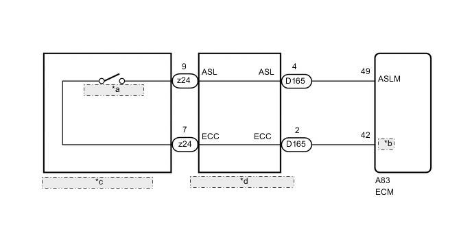
| *a | Speed Limiter Main Switch |
| *b | ECCS |
| *c | Steering Pad Switch Assembly |
| *d | Spiral with Sensor Cable Sub-assembly |
CAUTION / NOTICE / HINT
Note
The vehicle is equipped with a Supplemental Restraint System (SRS) which includes components such as airbags. Before servicing (including removal or installation of parts), be sure to read the precaution for Supplemental Restraint Systems Click here.
PROCEDURE
-
CHECK CRUISE CONTROL SYSTEM
-
Turn the ignition switch to ON.
-
Turn the cruise control switch on.
-
Check the operation of each function by operating the cruise control switch Click here.
OK Each function of the cruise control system operates normally.
NG 
GO TO CRUISE CONTROL SYSTEM Click here
OK 
-
-
READ VALUE USING GTS (SPEED LIMITER MAIN SWITCH)
-
Use the Data List to check if the warning canceling switch is functioning properly.
Cruise Control Tester Display Measurement Item/Range Normal Condition Diagnostic Note ASL Main Switch Speed limiter main switch signal / ON or OFF ON: Speed limiter main switch on
OFF: Speed limiter main switch off
- OK On screen, item changes between ON and OFF according to above chart.
NG 
INSPECT SPIRAL WITH SENSOR CABLE SUB-ASSEMBLY Click here
OK
-
-
CHECK DTC OUTPUT (CRUISE CONTROL SYSTEM)
-
Check for DTCs Click here.
OK DTC P0500 is not output. Result Result Proceed to OK (for 1WW) A OK (for 2WW) B NG C
A
REPLACE ECM Click here
B
REPLACE ECM Click here
C
GO TO CRUISE CONTROL SYSTEM Click here
-
-
INSPECT SPIRAL WITH SENSOR CABLE SUB-ASSEMBLY
-
Remove the spiral with sensor cable sub-assembly Click here.
-
Inspect the spiral with sensor cable sub-assembly Click here.
NG
REPLACE SPIRAL WITH SENSOR CABLE SUB-ASSEMBLY Click here
OK
-
-
INSPECT STEERING PAD SWITCH ASSEMBLY
-
Remove the steering pad switch assembly Click here.
-
Inspect the steering pad switch assembly Click here.
NG
REPLACE STEERING PAD SWITCH ASSEMBLY Click here
OK
-
-
CHECK HARNESS AND CONNECTOR (SPIRAL WITH SENSOR CABLE SUB-ASSEMBLY - ECM AND BODY GROUND)
-
Disconnect the D165 spiral with sensor cable sub-assembly connector.
-
Disconnect the A83 ECM connector.
-
Measure the resistance according to the value(s) in the table below.
Standard Resistance Tester Connection Condition Specified Condition D165-2 (ECC) - A83-42 (ECCS) Always Below 1 Ω D165-4 (ASL) - A83-49 (ASLM) D165-2 (ECC) or A83-42 (ECCS) - Body ground Always 10 kΩ or higher D165-4 (ASL) or A83-49 (ASLM) - Body ground Result Result Proceed to OK (for 1WW) A OK (for 2WW) B NG C
A
REPLACE ECM Click here
B
REPLACE ECM Click here
C
REPAIR OR REPLACE HARNESS OR CONNECTOR
-