CLEARANCE WARNING INDICATOR INSPECTION
PROCEDURE
INSPECT TELLTALE LIGHT ASSEMBLY
-
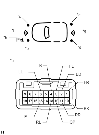
Inspect the indicator operation.
Apply battery voltage to the telltale light assembly connector, and check that the telltale light assembly indicator illuminates.
OK
Measurement Condition
Specified Condition
Battery positive (+) → Terminal 4 (B)
Battery negative (-) → Terminal 3 (FL)
Front left clearance sonar warning illuminates
Battery positive (+) → Terminal 4 (B)
Battery negative (-) → Terminal 1 (FR)
Front right clearance sonar warning illuminates
Battery positive (+) → Terminal 4 (B)
Battery negative (-) → Terminal 13 (RL)
Rear left clearance sonar warning illuminates
Battery positive (+) → Terminal 4 (B)
Battery negative (-) → Terminal 11 (RR)
Rear right clearance sonar warning illuminates
Battery positive (+) → Terminal 4 (B)
Battery negative (-) → Terminal 2 (BD)
Front sonar warning illuminates
Battery positive (+) → Terminal 4 (B)
Battery negative (-) → Terminal 10 (BK)
Back sonar warning illuminates
Battery positive (+) → Terminal 4 (B)
Battery negative (-) → Terminal 12 (OP)
Clearance sonar indicator illuminates
If the result is not as specified, replace the telltale light assembly (clearance warning indicator).
Table 1. Text in Illustration *a
Component without harness connected
(Telltale Light Assembly (clearance warning indicator))
*b
Front left clearance sonar warning
*c
Front right clearance sonar warning
*d
Rear left clearance sonar warning
*e
Rear right clearance sonar warning
*f
Front sonar warning
*g
Back sonar warning
*h
Clearance sonar indicator
Inspect the illumination operation.
Apply battery voltage to the telltale light assembly connector, and check that the telltale light assembly indicator illuminates.
OK
Measurement Condition
Specified Condition
Battery positive (+) → Terminal 6 (ILL+)
Battery negative (-) → Terminal 15 (E)
Illuminates
If the result is not as specified, replace the telltale light assembly (clearance warning indicator).
-