STEERING COLUMN ASSEMBLY REMOVAL
CAUTION / NOTICE / HINT
Some of these service operations affect the SRS airbag system. Read the precautionary notices concerning the SRS airbag system before servicing the steering wheel (Click hereClick here).
PROCEDURE
PLACE FRONT WHEELS FACING STRAIGHT AHEAD
DISCONNECT CABLE FROM NEGATIVE BATTERY TERMINAL
Disable the auto tilt away function by changing the customize parameter (Click here).
Note:Record the current customize parameter setting (whether the auto tilt away function is enabled or disabled) in order to restore the current setting after finishing the operation.
Tip:Performing the above operation causes the auto tilt away function to be disabled when the engine switch is turned off.
Turn the engine switch on (IG). Operate the tilt and telescopic switch to fully extend and lower the steering column assembly.
Turn the engine switch off and disconnect the cable from the negative (-) battery terminal.
CAUTION:Wait at least 90 seconds after disconnecting the cable from the negative (-) battery terminal to disable the SRS system.
Note:After turning the engine switch off, waiting time may be required before disconnecting the cable from the battery terminal. Therefore, make sure to read the disconnecting the cable from the battery terminal notice before proceeding with work (Click here).
When disconnecting the cable, some systems need to be initialized after the cable is reconnected (Click here).
REMOVE FRONT WHEEL LH
REMOVE STEERING WHEEL ASSEMBLY
Remove the steering wheel assembly (Click here).
REMOVE STEERING COLUMN LOWER COVER
-
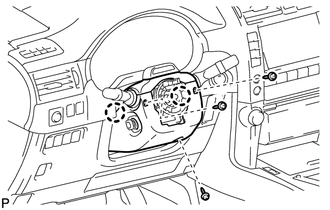
Remove the 3 screws.
Detach the 2 claws and remove the steering column lower cover.
Note:Do not damage the tilt and telescopic switch.
-
REMOVE STEERING COLUMN UPPER COVER
-
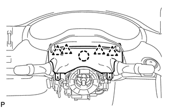
Detach the 4 clips.
Detach the claw and remove the steering column upper cover.
-
REMOVE COMBINATION SWITCH ASSEMBLY WITH SPIRAL CABLE SUB-ASSEMBLY
Disconnect the connectors from the combination switch with spiral cable.
-
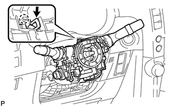
Use pliers to hold the clamp and raise the claw with a screwdriver. Then remove the combination switch switch assembly with spiral cable sub-assembly from the steering column assembly.
REMOVE NO. 1 INSTRUMENT LOWER PANEL AIRBAG ASSEMBLY
Remove the instrument lower panel airbag assembly (Click hereClick here).
REMOVE STEERING COLUMN ASSEMBLY (TILT STEERING GEAR ASSEMBLY WITH MOTOR)
Detach the claws and remove the wire harness protector and wire harness.
-
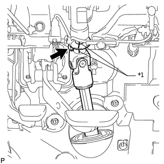
*1
Matchmark
Put matchmarks on the steering actuator and steering column.
Remove the bolt.
-
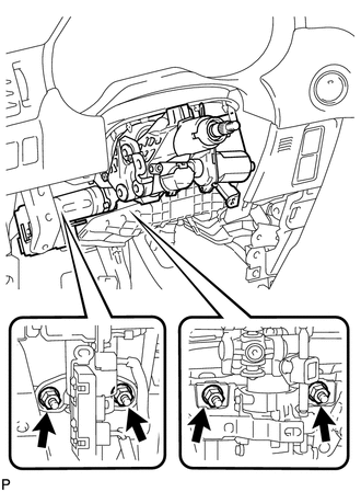
Remove the 4 nuts, steering column and steering shaft stopper.
REMOVE FRONT NO. 1 FENDER APRON TO FRAME SEAL LH
DISCONNECT STEERING INTERMEDIATE SHAFT ASSEMBLY
-
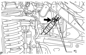
*1
Matchmark
Put matchmarks on the steering intermediate shaft and No. 2 steering intermediate shaft.
-
REMOVE NO. 1 STEERING COLUMN HOLE COVER SUB-ASSEMBLY
-
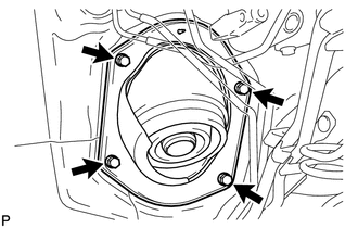
Remove the 4 bolts and steering column hole cover from the vehicle.
-
DISCONNECT NO. 2 STEERING INTERMEDIATE SHAFT SUB-ASSEMBLY
-
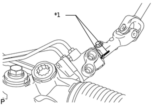
*1
Matchmark
Put matchmarks on the No. 2 steering intermediate shaft and power steering gear.
Remove the bolt and No. 2 steering intermediate shaft from the power steering gear.
-