CYLINDER HEAD GASKET REMOVAL
CAUTION / NOTICE / HINT
The necessary procedures (adjustment, calibration, initialization or registration) that must be performed after parts are removed and installed, or replaced during cylinder head gasket removal/installation are shown below.
| Replaced Part or Performed Procedure | Necessary Procedure | Effect/Inoperative Function when Necessary Procedure not Performed | Link |
|---|---|---|---|
| Battery terminal is disconnected/reconnected | Perform steering sensor zero point calibration | Lane departure alert system (w/ Steering Control) | |
| Pre-collision system | |||
| Memorize steering angle neutral point | Parking assist monitor system | ||
| Panoramic View Monitor System | |||
| Replacement of ECM | Vehicle Identification Number (VIN) registration | MIL comes on | |
| Perform code registration (Immobiliser system) | Engine start function | See Service Bulletin for the registration method. | |
|
Inspection after repair |
|
|
| Replacement of automatic transaxle assembly |
|
|
for Initialization for Registration |
| Replacement of ECM (If possible, read the transaxle compensation code from the previous ECM) |
|
||
| Replacement of ECM (If impossible, read the transaxle compensation code from the previous ECM) |
|
||
| Replacement of ECM | Perform code registration (Immobiliser function) |
|
See Service Bulletin for the registration method. |
| Suspension, tires, etc. (The vehicle height changes because of suspension or tire replacement) |
Rear television camera assembly optical axis (Back camera position setting) | Parking assist monitor system | for Initialization for Calibration |
|
Panoramic view monitor system | for Initialization for Calibration |
|
| Perform headlight ECU sub-assembly LH initialization | Lighting system (EXT) | ||
| Front wheel alignment adjustment | Perform system variant learning and acceleration sensor zero point calibration. |
|
*1: When the ECM is replaced with a new one, reset memory is unnecessary.
PROCEDURE
-
INSTALL ENGINE ASSEMBLY TO ENGINE STAND
-
REMOVE ENGINE HANGERS
-
REMOVE KNOCK CONTROL SENSOR
-
REMOVE IGNITION COIL ASSEMBLY
-
REMOVE VACUUM PUMP ASSEMBLY
-
REMOVE V-RIBBED BELT
-
REMOVE GENERATOR ASSEMBLY
-
REMOVE COMPRESSOR ASSEMBLY WITH MAGNETIC CLUTCH
-
REMOVE NO. 2 IDLER PULLEY SUB-ASSEMBLY
-
REMOVE V-RIBBED BELT TENSIONER ASSEMBLY
-
REMOVE WATER PUMP PULLEY
-
REMOVE ENGINE OIL LEVEL DIPSTICK GUIDE
-
REMOVE NO. 5 CYLINDER BLOCK INSULATOR (w/ Oil Cooler)
-
REMOVE WIRE HARNESS CLAMP BRACKET
-
REMOVE WATER FILLER BRACKET
-
REMOVE CRANKSHAFT PULLEY
-
REMOVE FRONT NO. 1 ENGINE MOUNTING BRACKET LH
-
DISCONNECT WATER BY-PASS HOSE
-
REMOVE WATER INLET WITH THERMOSTAT SUB-ASSEMBLY
-
REMOVE CAMSHAFT TIMING OIL CONTROL SOLENOID ASSEMBLY (for Intake Side of Bank 1)
-
REMOVE CAMSHAFT TIMING OIL CONTROL SOLENOID ASSEMBLY (for Exhaust Side of Bank 1)
-
REMOVE CAMSHAFT TIMING OIL CONTROL SOLENOID ASSEMBLY (for Exhaust Side of Bank 2)
-
REMOVE CAMSHAFT TIMING OIL CONTROL SOLENOID ASSEMBLY (for Intake Side of Bank 2)
-
REMOVE VVT SENSOR (for Intake Side of Bank 1)
-
REMOVE VVT SENSOR (for Exhaust Side of Bank 1)
-
REMOVE VVT SENSOR (for Intake Side of Bank 2)
-
REMOVE VVT SENSOR (for Exhaust Side of Bank 2)
-
REMOVE CRANKSHAFT POSITION SENSOR PROTECTOR
-
REMOVE SENSOR WIRE
-
REMOVE CYLINDER HEAD COVER SUB-ASSEMBLY
-
REMOVE CYLINDER HEAD COVER SUB-ASSEMBLY LH
-
REMOVE SPARK PLUG TUBE GASKET
-
REMOVE OIL COOLER ASSEMBLY (w/ Oil Cooler)
-
REMOVE OIL COOLER PIPE (w/ Oil Cooler)
-
REMOVE NO. 2 OIL PAN SUB-ASSEMBLY
-
REMOVE OIL STRAINER SUB-ASSEMBLY
-
REMOVE OIL PAN SUB-ASSEMBLY
-
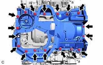
*a Nut Remove the 16 bolts and 2 nuts from the oil pan sub-assembly.
Note
Make sure to clean the bolts and stud bolts and check the threads for cracks or other damage.
-
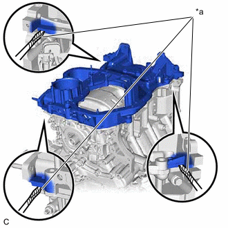
*a Protective Tape Remove the oil pan sub-assembly by prying between the oil pan sub-assembly and timing chain cover assembly or cylinder block sub-assembly with a screwdriver wrapped with protective tape.
Note
Be careful not to damage the contact surfaces of the cylinder block sub-assembly, timing chain cover assembly and oil pan sub-assembly.
-
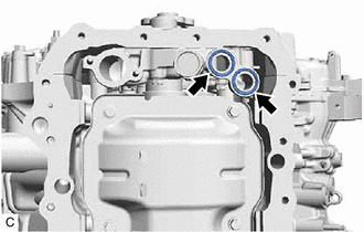
Remove the 2 oil pan gaskets from the timing chain cover assembly.
-
-
REMOVE TIMING CHAIN COVER ASSEMBLY
-
REMOVE TIMING CHAIN CASE OIL SEAL
-
SET NO. 1 CYLINDER TO TDC (COMPRESSION)
-
REMOVE NO. 1 CHAIN TENSIONER ASSEMBLY
-
REMOVE CHAIN TENSIONER SLIPPER
-
REMOVE CHAIN SUB-ASSEMBLY
-
REMOVE CAMSHAFT TIMING GEAR ASSEMBLY, CAMSHAFT TIMING EXHAUST GEAR ASSEMBLY AND NO. 2 CHAIN SUB-ASSEMBLY (for Bank 1)
-
REMOVE NO. 2 CHAIN TENSIONER ASSEMBLY
-
REMOVE CAMSHAFT BEARING CAP (for Bank 1)
-
REMOVE CAMSHAFT
-
REMOVE NO. 2 CAMSHAFT
-
REMOVE CAMSHAFT HOUSING SUB-ASSEMBLY
-
REMOVE CAMSHAFT TIMING GEAR ASSEMBLY, CAMSHAFT TIMING EXHAUST GEAR ASSEMBLY AND NO. 2 CHAIN SUB-ASSEMBLY (for Bank 2)
-
REMOVE NO. 3 CHAIN TENSIONER ASSEMBLY
-
REMOVE CAMSHAFT BEARING CAP (for Bank 2)
-
REMOVE NO. 3 CAMSHAFT SUB-ASSEMBLY
-
REMOVE NO. 4 CAMSHAFT SUB-ASSEMBLY
-
REMOVE CAMSHAFT HOUSING SUB-ASSEMBLY LH
-
REMOVE SENSOR WIRE
-
REMOVE NO. 1 CHAIN VIBRATION DAMPER
-
REMOVE NO. 2 CHAIN VIBRATION DAMPER
-
REMOVE NO. 1 VALVE ROCKER ARM SUB-ASSEMBLY
-
REMOVE VALVE LASH ADJUSTER ASSEMBLY
-
REMOVE VALVE STEM CAP
-
REMOVE WATER OUTLET
-
REMOVE CYLINDER HEAD SUB-ASSEMBLY
-
REMOVE CYLINDER HEAD GASKET
-
Remove the cylinder head gasket from the cylinder block sub-assembly.
-
-
REMOVE CYLINDER HEAD LH
-
REMOVE NO. 2 CYLINDER HEAD GASKET
-
Remove the No. 2 cylinder head gasket from the cylinder block sub-assembly.
-
-
INSPECT CYLINDER HEAD SET BOLT