BODY STRUCTURE
-
CONSTRUCTION
-
Deck
-
The position of the body's structural parts is optimized and reinforcing materials are provided, creating a body structure with high rigidity and ensuring driving stability.
-
A deck with toughness is created by reinforcing the following areas of the deck.
-
A bead shape (*a in illustration) is provided on the wheelhouse.
-
A rear body guard plate (*1 in illustration) is provided on the header board assembly (*2 in illustration).
-
A sill crossmember (*3 in illustration) is provided on the rear floor assembly (*4 in illustration).
-
A tail gate service hole cover (*5 in illustration) with the optimal shape is provided.
-
The thickness of the rear body side panel (*6 in illustration) has been optimized.
Figure 1. Double Cab
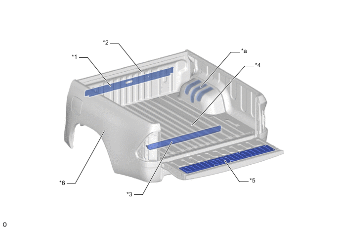
*1 Rear Body Guard Plate *2 Header Board Assembly *3 Sill Crossmember (Cross Sill Assembly No. 2) *4 Rear Floor Assembly *5 Tail Gate Service Hole Cover *6 Rear Body Side Panel *a Bead Shape - - Figure 2. Smart Cab
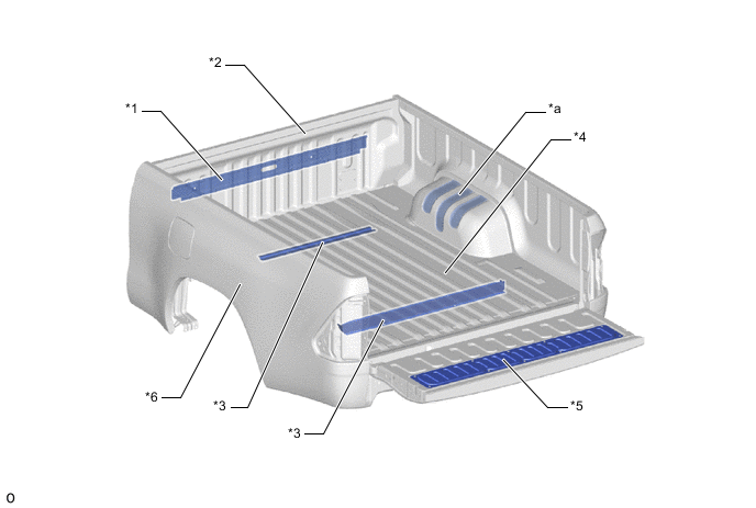
*1 Rear Body Guard Plate *2 Header Board Assembly *3 Sill Crossmember (Front: Cross Sill Assembly No. 12/Rear: Cross Sill Assembly No. 2) *4 Rear Floor Assembly *5 Tail Gate Service Hole Cover *6 Rear Body Side Panel *a Bead Shape - - Figure 3. Single Cab
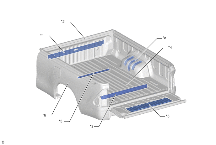
*1 Rear Body Guard Plate *2 Header Board Assembly *3 Sill Crossmember (Front: Cross Sill Assembly No. 12/Rear: Cross Sill Assembly No. 2) *4 Rear Floor Assembly *5 Tail Gate Service Hole Cover *6 Rear Body Side Panel *a Bead Shape - -
-
-
-
Spot Welding
-
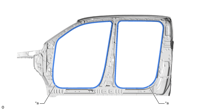
An increased number of spot welding points are provided throughout the body, increasing the connectivity of the panels and ensuring superior driving stability (yaw response, rear grip feeling, steering response and hand feedback).
Figure 4. Spot Welding 1
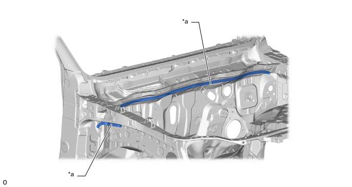
*a Increased Number of Spot Welding Points - - Figure 5. Spot Welding 2 (The illustration shows an example)
*a Increased Number of Spot Welding Points - -
-
-
Frame
-
The overload capacity has increased compared to a conventional vehicle by increasing the height of the side rail cross section (*d in illustration). Also, as a result, a sufficient strength is ensured even against a strong force from road impact.
Figure 6. Frame 1 (The illustration shows an example)
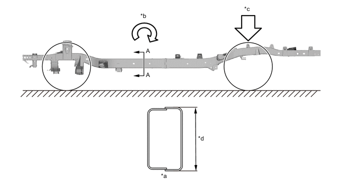
*a A - A Cross Section *b Longitudinal Bending *c Overload Capacity *d Height of Side Rail -
The crossmember and side rail connectivity is strengthened and a highly rigid frame structure is created by using all round welding at each crossmember and side rail welding spot.
Figure 7. Frame 2 (The illustration shows an example)
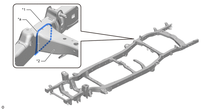
*1 Side Rail *2 Crossmember *a All Round Welding - -
-
-