HYBRID VEHICLE TRANSAXLE UNIT DISASSEMBLY

CAUTION / NOTICE / HINT
Note
-
Do not use gloves, cloths or papers that produce lint or dust.
-
Cover the removed parts with plastic bags to prevent entry of foreign matter.
-
Do not remove the generator cable terminal, motor cable terminal, transaxle housing cover, rear transaxle case cover sub-assembly or resolver adjuster bolts.
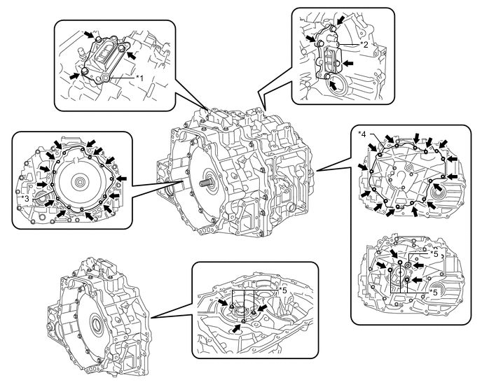
Text in Illustration *1 Generator Cable Terminal *2 Motor Cable Terminal *3 Transaxle Housing Cover *4 Rear Transaxle Case Cover Sub-assembly *5 Resolver Adjuster Bolt - -
PROCEDURE
-
INSPECT INPUT SHAFT END PLAY
-
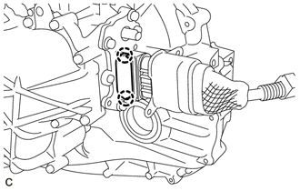
REMOVE GENERATOR CABLE
-
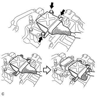
Remove the 3 bolts and slide the generator cable connector shell back.
-
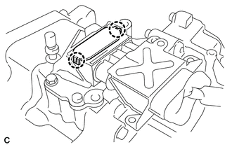
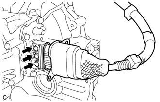
Disengage the 2 claws to remove the terminal cap from the hybrid vehicle transaxle assembly.
-
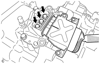
Remove the 3 bolts and generator cable from the hybrid vehicle transaxle assembly.
Note
Keep foreign matter, water, etc. away from the terminal cable and its installation section.
-
-
REMOVE MOTOR CABLE
-
Remove the 3 bolts and slide the motor cable connector shell back.
-
Disengage the 2 claws to remove the terminal cap from the hybrid vehicle transaxle assembly.
-
Remove the 3 bolts and motor cable from the hybrid vehicle transaxle assembly.
Note
Keep foreign matter, water, etc. away from the terminal cable and its installation section.
-
-
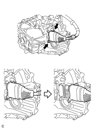
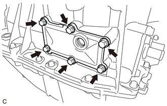
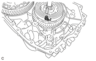
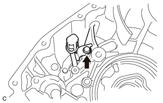
REMOVE SHIFT CONTROL ACTUATOR ASSEMBLY
-
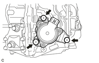
Remove the 3 shift control actuator bolts and shift control actuator assembly from the hybrid vehicle transaxle assembly.
Tech Tips
-
Please refer to Service Bulletin for details on the removal procedure of the shift control actuator bolt.
-
This actuator is a precision instrument. Do not strike it with a plastic hammer or the like during installation.
-
This actuator detects its own position when a battery is reinstalled. Thus it does not require initialization.
-
-
-
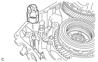
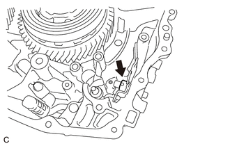
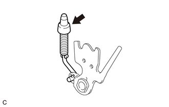
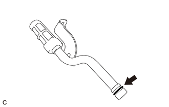
REMOVE TRANSAXLE BREATHER PLUG
-
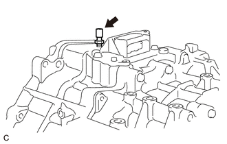
Remove the transaxle breather plug from the hybrid vehicle transaxle assembly.
Note
Be careful not to damage the transaxle breather plug.
-
-
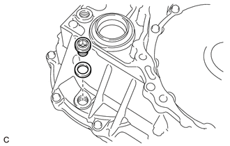
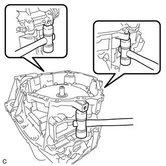
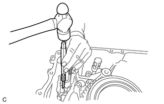
REMOVE WITH HEAD STRAIGHT SCREW PLUG
-
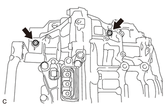
Using a 6 mm hexagon socket wrench, remove the 2 with head straight screw plugs from the hybrid vehicle transaxle assembly.
-
-
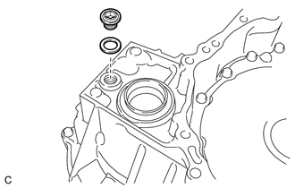
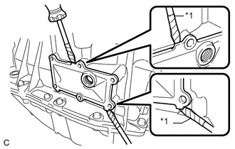
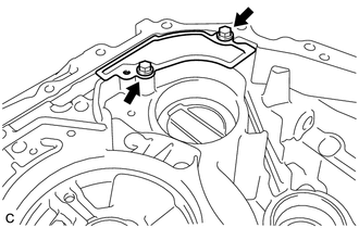
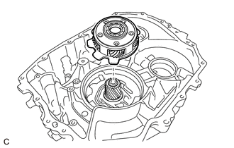
REMOVE TRANSMISSION OIL PUMP COVER SUB-ASSEMBLY
-
Remove the fluid pump cover plug and O-ring from the transmission oil pump cover sub-assembly.
-
Remove the 4 bolts and transmission oil pump cover sub-assembly from the hybrid vehicle transaxle assembly.
Note
Do not drop the transaxle oil pump drive rotor or transmission oil pump driven rotor.
-
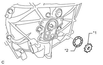
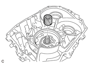
Text in Illustration *1 Transaxle Oil Pump Drive Rotor *2 Transmission Oil Pump Driven Rotor Remove the transaxle oil pump drive rotor and transmission oil pump driven rotor from the hybrid vehicle transaxle assembly.
-
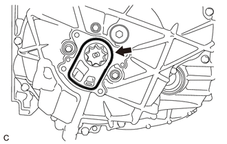
Remove the O-ring from the hybrid vehicle transaxle assembly.
-
-
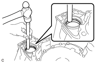
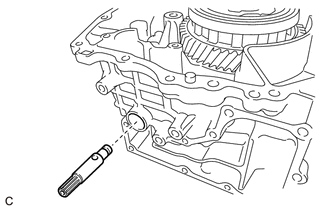
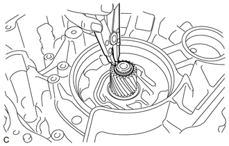
REMOVE OIL PUMP DRIVE SHAFT
-
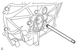
Remove the oil pump drive shaft from the hybrid vehicle transaxle assembly.
-
-
SECURE HYBRID VEHICLE TRANSAXLE ASSEMBLY
-
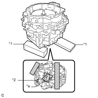
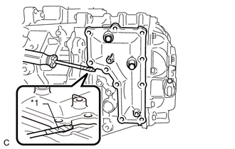
Text in Illustration *1 Wooden Block *2 Resolver Sensor Connector *a Installation area of the Transmission Oil Pump Cover Sub-assembly 
Wooden Block Placement Position Place wooden blocks under the hybrid vehicle transaxle assembly.
Note
Do not place the wooden blocks under the installation area of the transmission oil pump cover sub-assembly or resolver sensor connector.
-
-
REMOVE FILLER PLUG
-
Using a 10 mm hexagon socket wrench, remove the filler plug and gasket from the hybrid vehicle transaxle assembly.
-
-
REMOVE DRAIN PLUG
-
Using a 10 mm hexagon socket wrench, remove the drain plug and gasket from the hybrid vehicle transaxle assembly.
-
-
REMOVE NO. 1 MOTOR WATER JACKET COVER ASSEMBLY
-
Using a 10 mm hexagon socket wrench, remove the drain plug and gasket from the No. 1 motor water jacket cover assembly.
-
Remove the 6 bolts from the No. 1 motor water jacket cover assembly.
-
Text in Illustration *1 Protective Tape Using a screwdriver, remove the No. 1 motor water jacket cover assembly from the hybrid vehicle transaxle assembly.
Note
Be careful not to damage the hybrid vehicle transaxle assembly.
Tech Tips
Tape the screwdriver tip before use.
-
-
REMOVE NO. 2 MOTOR WATER JACKET COVER ASSEMBLY
-
Remove the 6 bolts from the No. 2 motor water jacket cover assembly.
-
Text in Illustration *1 Protective Tape Using a screwdriver, remove the No. 2 motor water jacket cover assembly from the hybrid vehicle transaxle assembly.
Note
Be careful not to damage the hybrid vehicle transaxle assembly.
Tech Tips
Tape the screwdriver tip before use.
-
-
REMOVE MOTOR WATER JACKET COVER ASSEMBLY
-
Remove the 10 bolts from the motor water jacket cover assembly.
-
Text in Illustration *1 Protective Tape Using a screwdriver, remove the motor water jacket cover assembly from the hybrid vehicle transaxle assembly.
Note
Be careful not to damage the hybrid vehicle transaxle assembly.
Tech Tips
Tape the screwdriver tip before use.
-
-
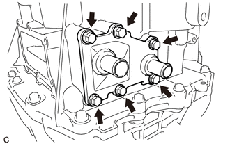
REMOVE HYBRID VEHICLE GENERATOR ASSEMBLY
-
Install the No. 1 engine hanger and No. 2 engine hanger with the 2 bolts and washer as shown in the illustration.
Text in Illustration *1 No. 1 Engine Hanger *2 No. 2 Engine Hanger *3 Washer - - - Torque:
- 43 N*m { 438 kgf*cm, 32 ft.*lbf }
Part Name Part No. No. 1 Engine Hanger 12281-37050 No. 2 Engine Hanger 12282-37040 Bolt 91552-81050 Tech Tips
When installing the No. 1 engine hanger, use a washer with an appropriate thickness so that the No. 1 engine hanger will not interfere with the installation surface of the transaxle housing.
-
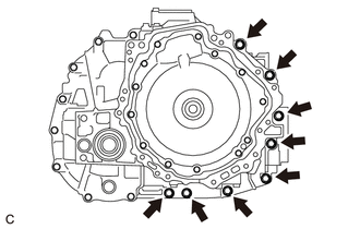
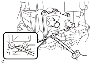
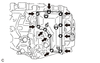
Remove the 8 bolts from the hybrid vehicle generator assembly.
-
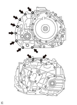
Remove the 8 bolts from the hybrid vehicle generator assembly.
-
Remove the 2 bolts from the hybrid vehicle motor assembly.
-
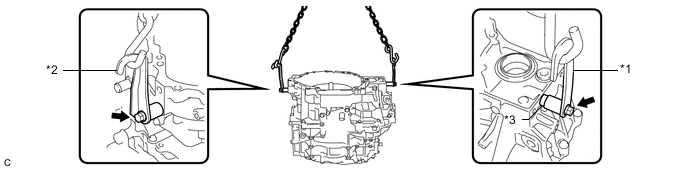
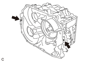
While lifting the hybrid vehicle generator assembly with a chain, tap the areas shown in the illustration with a plastic hammer and separate the hybrid vehicle generator assembly from the hybrid vehicle motor assembly.
-
While lifting the hybrid vehicle generator assembly with a chain, remove it from the hybrid vehicle motor assembly.
Note
-
Lift the hybrid vehicle generator assembly straight up.
-
If the hybrid vehicle generator assembly is tilted, return it to the original position before removing.
-
-
Remove the 2 bolts, washer, No. 1 engine hanger and No. 2 engine hanger from the hybrid vehicle generator assembly.
-
-
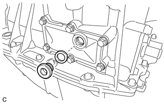
REMOVE TRANSAXLE HOUSING OIL SEPARATOR
-
Remove the 2 bolts and transaxle housing oil separator from the hybrid vehicle generator assembly.
-
-
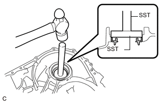
REMOVE HYBRID VEHICLE TRANSAXLE ASSEMBLY TYPE T OIL SEAL (RH SIDE)
-
Using SST and a hammer, remove the hybrid vehicle transaxle assembly type T oil seal (RH side) from the hybrid vehicle generator assembly.
- SST
- 09950-60010 ( 09951-00590 )
- 09950-70010 ( 09951-07200 )
-
-
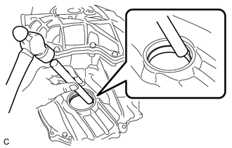
REMOVE TAPERED ROLLER BEARING (RH SIDE OUTER RACE)
-
Using brass bar and a hammer, remove the tapered roller bearing (RH side outer race) and differential case RH shim from the hybrid vehicle generator assembly.
Note
Be careful not to damage the hybrid vehicle generator assembly.
-
-
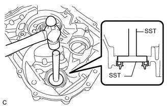
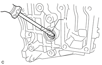
REMOVE INPUT SHAFT TYPE T OIL SEAL
-
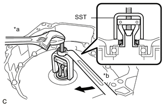
Text in Illustration *a Hold *b Turn Using SST, remove the input shaft type T oil seal from the hybrid vehicle generator assembly.
- SST
- 09310-36021
Note
-
Be careful not to damage the hybrid vehicle generator assembly.
-
When removing the hybrid vehicle generator assembly, be sure to replace the input shaft type T oil seal.
-
-
REMOVE COUNTER DRIVEN GEAR SHIM
-
Remove the counter driven gear shim from the counter driven gear sub-assembly.
-
-
REMOVE PARKING LOCK PAWL
-
Remove the parking lock pawl and parking lock pawl shaft from the hybrid vehicle motor assembly.
-
-
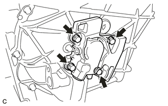
REMOVE PAWL STOPPER PLATE
-
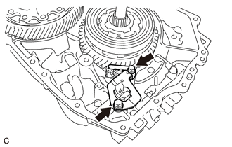
Remove the 2 bolts and pawl stopper plate from the hybrid vehicle motor assembly.
-
-
REMOVE TORSION SPRING
-
Remove the parking lock pawl shaft and torsion spring from the hybrid vehicle motor assembly.
-
-
REMOVE PARKING LOCK SLEEVE
-
Remove the parking lock sleeve from the hybrid vehicle motor assembly.
-
-
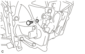
REMOVE MANUAL DETENT SPRING SUB-ASSEMBLY
-
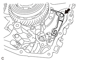
Remove the bolt and manual detent spring sub-assembly from the hybrid vehicle motor assembly.
-
-
REMOVE RETAINER SPRING
-
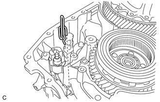
Remove the retainer spring from the hybrid vehicle motor assembly and No. 1 parking lock shaft.
-
-
REMOVE NO. 1 PARKING LOCK SHAFT
-
Using a hammer and a screwdriver, cut off the spacer and remove it from the No. 1 parking lock shaft.
-
Using a 5 mm pin punch and a hammer, drive out the slotted spring pin from the No. 1 parking lock shaft.
-
Remove the No. 1 parking lock shaft from the hybrid vehicle motor assembly.
-
-
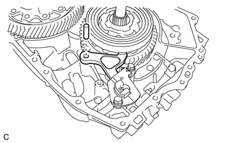
REMOVE PARKING LOCK ROD SUB-ASSEMBLY
-
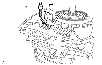
Text in Illustration *1 No. 1 Parking Lock Lever Sub-assembly *2 Parking Lock Rod Sub-assembly Remove the No. 1 parking lock lever sub-assembly and parking lock rod sub-assembly from the hybrid vehicle motor assembly.
-
Remove the parking lock rod sub-assembly from the No. 1 parking lock lever sub-assembly.
-
-
REMOVE NO. 1 TRANSMISSION MAGNET
-
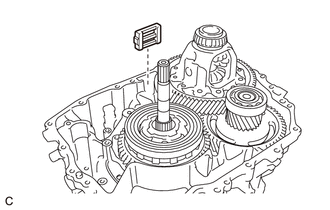
Remove the No. 1 transmission magnet from the hybrid vehicle motor assembly.
-
-
REMOVE INPUT SHAFT ASSEMBLY
-
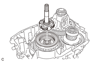
Remove the input shaft assembly from the counter drive gear sub-assembly.
-
-
REMOVE PLANETARY SUN GEAR
-
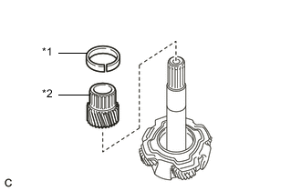
Text in Illustration *1 Planetary Sun Gear Snap Ring *2 Planetary Sun Gear Remove the planetary sun gear snap ring and planetary sun gear from the input shaft assembly.
-
-
REMOVE THRUST NEEDLE ROLLER BEARING
-
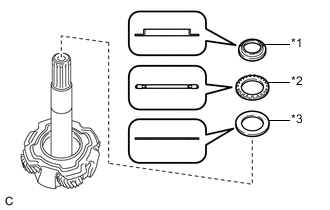
Text in Illustration *1 Thrust Bearing Race *2 Thrust Needle Roller Bearing *3 No. 1 Thrust Bearing Race Remove the thrust bearing race, thrust needle roller bearing and No. 1 thrust bearing race from the input shaft assembly.
Tech Tips
The No. 1 thrust bearing race may be attached to the input shaft assembly.
-
-
REMOVE DIFFERENTIAL CASE SUB-ASSEMBLY
-
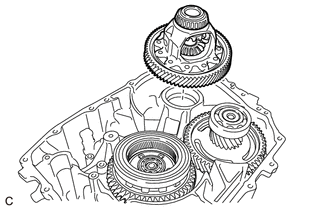
Remove the differential case sub-assembly from the hybrid vehicle motor assembly.
-
-
REMOVE COUNTER DRIVEN GEAR SUB-ASSEMBLY
-
Remove the counter driven gear sub-assembly from the hybrid vehicle motor assembly.
-
-
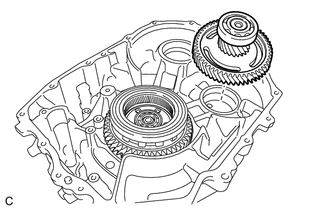
REMOVE COUNTER DRIVE GEAR SUB-ASSEMBLY
-
Remove the counter drive gear sub-assembly from the No. 1 rear planetary gear assembly.
-
-
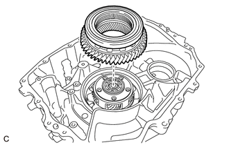
REMOVE NO. 1 REAR PLANETARY GEAR ASSEMBLY
-
Remove the No. 1 rear planetary gear assembly from the rear planetary sun gear.
-
-
INSPECT NO. 1 REAR PLANETARY GEAR ASSEMBLY
-
REMOVE REAR PLANETARY SUN GEAR
-
Using a snap ring expander, remove the rear planetary sun gear shaft snap ring from the hybrid vehicle motor assembly.
-
Remove the rear planetary sun gear from the hybrid vehicle motor assembly.
-
-
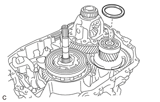
REMOVE TRANSMISSION OIL STRAINER
-
Remove the bolt and transmission oil strainer from the hybrid vehicle motor assembly.
-
Remove the O-ring from the transmission oil strainer
-
-
REMOVE HYBRID VEHICLE TRANSAXLE ASSEMBLY TYPE T OIL SEAL (LH SIDE)
-
Using SST and a hammer, remove the hybrid vehicle transaxle assembly type T oil seal (LH side) from the hybrid vehicle motor assembly.
- SST
- 09950-60010 ( 09951-00620 )
- 09950-70010 ( 09951-07200 )
-
-
REMOVE TAPERED ROLLER BEARING (LH SIDE OUTER RACE)
-
Using brass bar and a hammer, remove the tapered roller bearing (LH side outer race) from the hybrid vehicle motor assembly.
Note
Be careful not to damage the hybrid vehicle motor assembly.
-
-
REMOVE SHIFT CONTROL ACTUATOR SEAL
-
Text in Illustration *1 Protective Tape Using a screwdriver, remove the shift control actuator seal from the hybrid vehicle motor assembly.
Note
Be careful not to damage the hybrid vehicle motor assembly.
Tech Tips
Tape the screwdriver tip before use.
-
-
REMOVE TAPERED ROLLER BEARING (RH SIDE INNER RACE)
-
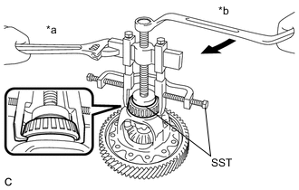
Text in Illustration *a Hold *b Turn Using SST, remove the tapered roller bearing (RH side inner race) from the differential case sub-assembly.
- SST
- 09950-40011 ( 09951-04010, 09952-04010, 09953-04030, 09954-04010, 09955-04061, 09957-04010, 09958-04011 )
- 09950-60010 ( 09951-00460 )
-
-
REMOVE TAPERED ROLLER BEARING (LH SIDE INNER RACE)
-
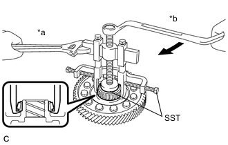
Text in Illustration *a Hold *b Turn Using SST, remove the tapered roller bearing (LH side inner race) from the differential case sub-assembly.
- SST
- 09950-40011 ( 09951-04010, 09952-04010, 09953-04030, 09954-04010, 09955-04061, 09957-04010, 09958-04011 )
- 09950-60010 ( 09951-00460 )
-
-
REMOVE RADIAL BALL BEARING (LH SIDE)
-
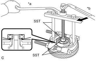
Text in Illustration *a Hold *b Turn Using SST, remove the radial ball bearing (LH side) from the counter driven gear sub-assembly.
- SST
- 09950-00020
- 09950-00030
- 09950-40011 ( 09957-04010 )
- 09950-60010 ( 09951-00280 )
-
-
REMOVE RADIAL BALL BEARING (RH SIDE)
-
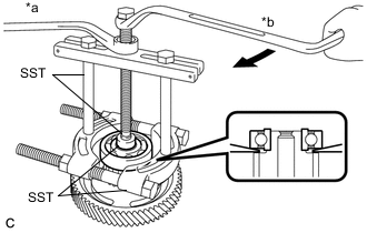
Text in Illustration *a Hold *b Turn Using SST, remove the radial ball bearing (RH side) from the counter driven gear sub-assembly.
- SST
- 09950-00020
- 09950-00030
- 09950-40011 ( 09957-04010 )
- 09950-60010 ( 09951-00280 )
-
-
REMOVE STRAIGHT PIN
-
Remove the 2 straight pins from the hybrid vehicle motor assembly.
-