HEATER SWITCH(w/ Combustion Type Power Heater) INSPECTION
PROCEDURE
INSPECT HEATER SWITCH ASSEMBLY
-
Disconnect the connector from the heater switch assembly.
Measure the resistance according to the value(s) in the table below.
Standard Resistance
Tester connection
Condition
Specified condition
4 (IG) - 1 (IN)
Heater switch ON
Below 1 Ω
4 (IG) - 1 (IN)
Heater switch OFF
10 kΩ or higher
If the result is not as specified, replace the heater switch assembly.
Check that the heater switch assembly operation indicator comes on.
Connect the positive (+) lead from the battery to terminal 1 (IN) and the negative (-) lead to terminal 5 (E), and check that the operation indicator comes on.
If the indicator does not come on, replace the heater switch assembly.
Check that the heater switch assembly illumination comes on.
Connect the positive (+) lead from the battery to terminal 3 (ILL+) and the negative (-) lead to terminal 2 (ILL-), and check that the switch illumination comes on.
If the illumination does not come on, replace the heater switch assembly.
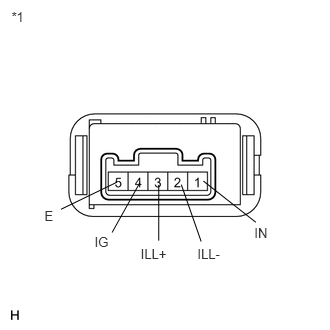
Table 1. Text in Illustration *1
Component without harness connected
(Heater Switch Assembly)
-