STARTER (for 1.6 kW Type) INSPECTION
-
INSPECT STARTER
CAUTION:
These tests must be performed within 3 to 5 seconds to prevent the coil from burning out.
-
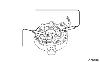
Perform pull-in/holding test.
-
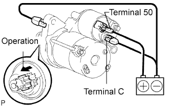
Disconnect the lead wire from terminal C.
-
Connect the battery to the magnet starter switch assembly as shown in the illustration. Then check that the clutch pinion gear moves outward.
If the clutch pinion gear does not move, replace the repair service starter kit.
-
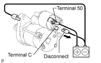
When the battery is connected as above with the clutch pinion gear out, disconnect the negative (-) lead from terminal C. Check that the pinion gear remains out.
If the clutch pinion gear moves inward, replace the repair service starter kit.
-
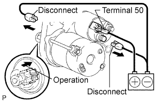
Disconnect the negative (-) lead from the starter body. Check that the clutch pinion gear returns inward.
If the clutch pinion gear does not return inward, replace the repair service starter kit.
-
-
Perform operation test without load.
-
Connect the lead wire to terminal C.
- Torque:
- 10 N*m { 102 kgf*cm, 7 ft.*lbf }
-
Mount the starter in a vise between aluminum plates.
-
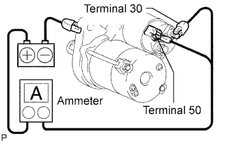
Connect the battery and an ammeter to the starter as shown in the illustration.
-
Check that the starter rotates smoothly and steadily while the pinion gear is moving out. Then measure the current.
Standard current 90 A or less at 11.5 V If the result is not as specified, replace the starter assembly.
-
-
-
INSPECT STARTER ARMATURE ASSEMBLY
-
Check the resistance.
-
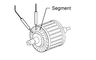
Measure the resistance between the segments.
Standard resistance Below 1 Ω If the result is not as specified, replace the armature assembly.
-
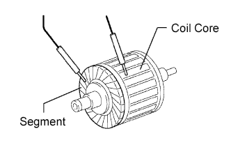
Measure the resistance between the segments and coil core.
Standard resistance 10 kΩ or higher If the result is not as specified, replace the armature assembly.
-
-
Check the commutator surface for dirt or burns.
If the surface is dirty or burnt, smooth the surface with 400-grit sandpaper or a lathe.
-
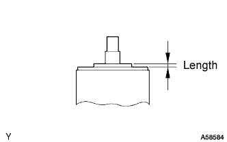
Using a vernier caliper, measure the protrusion length.
Standard length 3.1 mm (0.122 in.) Maximum length 3.8 mm (0.150 in.) If the length is greater than the maximum, replace the armature assembly.
-
-
INSPECT STARTER COMMUTATOR END FRAME ASSEMBLY
-
Check the brush length.
-
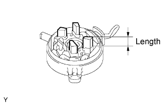
Using a vernier caliper, measure the brush length.
Standard length 9.0 mm (0.354 in.) Minimum length 4.0 mm (0.158 in.) If the length is less than the minimum, replace the commutator end frame assembly.
-
-
Check the resistance.
-
Measure the resistance between the positive (+) and negative (-) brushes.
Standard resistance 10 kΩ or higher If the result is not as specified, repair or replace the commutator end frame assembly.
-
-
-
INSPECT STARTER CENTER BEARING CLUTCH SUB-ASSEMBLY
-
Check the gear teeth on the planetary gears, and the internal gear and pinion gear of the starter center bearing clutch for wear or damage
If any of the gears is damaged, replace the center bearing clutch sub-assembly.
-
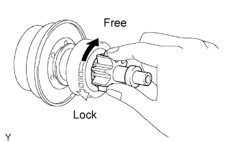
Check the starter center bearing clutch pinion gear.
-
Hold the starter center bearing clutch and rotate the pinion gear clockwise, and check that it turns freely. Try to rotate the pinion gear counterclockwise and check that it locks.
If the result is not as specified, replace the center bearing clutch sub-assembly.
-
-
-
INSPECT REPAIR SERVICE STARTER KIT
-
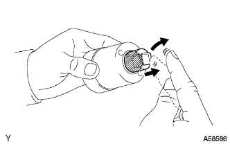
Check the plunger.
-
Push in the plunger and check that it returns quickly to its original position.
If the result is not as specified, replace the repair service starter kit.
-
-
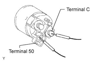
Check the resistance.
-
Measure the resistance between terminal 50 and terminal C.
Standard resistance Below 1 Ω If the result is not as specified, replace the repair service starter kit.
-
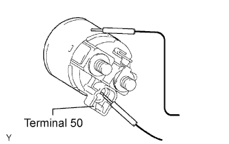
Measure the resistance between terminal 50 and the repair service starter kit body.
Standard resistance Below 2 Ω If the result is not as specified, replace the repair service starter kit.
-
-