CAN COMMUNICATION SYSTEM(w/o Central Gateway ECU) TERMINALS OF ECU
After turning the ignition switch off, waiting time may be required before disconnecting the cable from the negative (-) battery terminal. Therefore, make sure to read the disconnecting the cable from the negative (-) battery terminal notices before proceeding with work.
Turn the ignition switch off before measuring the resistances between CAN main bus lines and between CAN branch lines.
Turn the ignition switch off before inspecting CAN bus lines for a short to ground.
Before measuring the resistance of the CAN bus, turn the ignition switch off and leave the vehicle for 1 minute or more without operating the key or any switches, or opening or closing the doors. After that, disconnect the cable from the negative (-) battery terminal and leave the vehicle for 1 minute or more before measuring the resistance.
This section describes the standard values for all CAN related components.
Operating the ignition switch, any other switches or a door triggers related ECU and sensor communication on the CAN. This communication will cause the resistance value to change.
Even after DTCs are cleared, if a DTC is stored again after driving the vehicle for a while, the malfunction may be occurring due to vibration of the vehicle. In such a case, wiggling the ECUs or wire harness while performing the inspection below may help determine the cause of the malfunction.
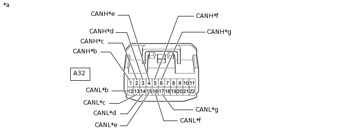
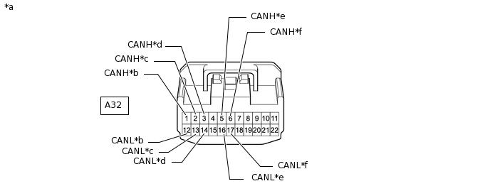
NO. 1 CAN JUNCTION CONNECTOR (for LHD Sedan)
Check the No. 1 CAN junction connector.
Connection diagram
*a
Front view of wire harness connector
(to No. 1 CAN Junction Connector)
*b
to No. 3 CAN Junction Connector
*c
to DLC3
*d
to Main Body ECU (Multiplex Network Body ECU)
*e
to Headlight Leveling ECU Assembly
(for Sedan with Automatic Headlight Beam Level Control System)
to Headlight Swivel ECU Assembly
(except Sedan with Automatic Headlight Beam Level Control System)
*f
to Brake Actuator Assembly
*g
to ECM
-
-
Check the connection diagram of the components which are connected to the No. 1 CAN junction connector.
Terminal No. (Symbol)
Wiring Color
Connected to
A32-1 (CANH)
L
No. 3 CAN junction connector
A32-12 (CANL)
W
A32-2 (CANH)
R
DLC3
A32-13 (CANL)
W
A32-3 (CANH)
G
Main body ECU (multiplex network body ECU)
A32-14 (CANL)
W
A32-4 (CANH)
Y
Headlight leveling ECU assembly*1
Headlight swivel ECU assembly*2
A32-15 (CANL)
W
A32-5 (CANH)
V
Brake actuator assembly
A32-16 (CANL)
W
A32-6 (CANH)
B
ECM
A32-17 (CANL)
W
*1: for Sedan with Automatic Headlight Beam Level Control System
*2: except Sedan with Automatic Headlight Beam Level Control System
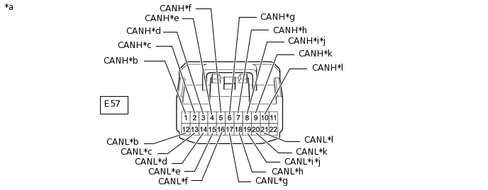
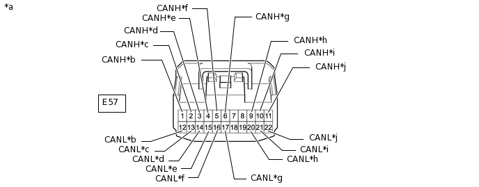
NO. 3 CAN JUNCTION CONNECTOR (for LHD Sedan)
Check the No. 3 CAN junction connector.
Connection diagram
*a
Front view of wire harness connector
(to No. 3 CAN Junction Connector)
*b
to Airbag Sensor Assembly
*c
to Air Conditioning Amplifier Assembly
(w/ Air Conditioning System)
*d
to Radio and Display Receiver Assembly
(for Radio and Display Type)
*e
to Combination Meter Assembly
*f
to No. 1 CAN Junction Connector
*g
to Certification ECU (Smart Key ECU Assembly)
(w/ Entry and Start System)
*h
to Clearance Warning ECU Assembly
(w/ Simple Intelligent Parking Assist System)
*i
to Engine Stop and Start ECU
(w/ Stop and Start System)
*j
to Telematics Transceiver
(w/ Manual (SOS) Switch)
*k
to Power Steering ECU Assembly
*l
to Steering Sensor (Spiral Cable with Sensor Sub-assembly)
(w/ VSC)
Check the connection diagram of the components which are connected to the No. 3 CAN junction connector.
Terminal No. (Symbol)
Wiring Color
Connected to
E57-1 (CANH)
V
Airbag sensor assembly
E57-12 (CANL)
W
E57-2 (CANH)
Y
Air conditioning amplifier assembly*1
E57-13 (CANL)
W
E57-3 (CANH)
Y
Radio and display receiver assembly*2
E57-14 (CANL)
W
E57-4 (CANH)
LG
Combination meter assembly
E57-15 (CANL)
W
E57-5 (CANH)
L
No. 1 CAN junction connector
E57-16 (CANL)
W
E57-6 (CANH)
R
Certification ECU (smart key ECU assembly)*3
E57-17 (CANL)
W
E57-7 (CANH)
B
Clearance warning ECU assembly*4
E57-18 (CANL)
W
E57-8 (CANH)
P
Engine stop and start ECU*5
E57-19 (CANL)
W
E57-8 (CANH)
G
Telematics transceiver*6
E57-19 (CANL)
W
E57-9 (CANH)
GR
Power steering ECU assembly
E57-20 (CANL)
W
E57-10 (CANH)
SB
Steering sensor (spiral cable with sensor sub-assembly)*7
E57-21 (CANL)
W
*1: w/ Air Conditioning System
*2: for Radio and Display Type
*3: w/ Entry and Start System
*4: w/ Simple Intelligent Parking Assist System
*5: w/ Stop and Start System
*6: w/ Manual (SOS) Switch
*7: w/ VSC
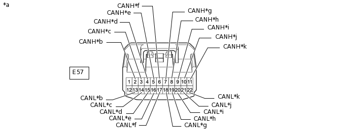
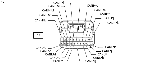
NO. 3 CAN JUNCTION CONNECTOR (for LHD except Sedan)
Check the No. 3 CAN junction connector.
Connection diagram
*a
Front view of wire harness connector
(to No. 3 CAN Junction Connector)
*b
to Air Conditioning Amplifier Assembly
(w/ Automatic Air Conditioning System)
*c
to Radio and Display Receiver Assembly
(for Radio and Display Type)
*d
to Combination Meter Assembly
*e
to No. 4 CAN Junction Connector
*f
to Certification ECU (Smart Key ECU Assembly)
(w/ Entry and Start System)
*g
to Airbag Sensor Assembly
*h
to Engine Stop and Start ECU
(w/ Stop and Start System)
*i
to Power Steering ECU Assembly
*j
to Steering Sensor (Spiral Cable with Sensor Sub-assembly)
*k
to Pre-crash Safety City Sensor
(w/ Toyota Safety Sense)
-
-
Check the connection diagram of the components which are connected to the No. 3 CAN junction connector.
Terminal No. (Symbol)
Wiring Color
Connected to
E57-2 (CANH)
Y
Air conditioning amplifier assembly*1
E57-13 (CANL)
W
E57-3 (CANH)
G
Radio and display receiver assembly*2
E57-14 (CANL)
W
E57-4 (CANH)
LG
Combination meter assembly
E57-15 (CANL)
W
E57-5 (CANH)
L
No. 4 CAN junction connector
E57-16 (CANL)
W
E57-6 (CANH)
R
Certification ECU (smart key ECU assembly)*3
E57-17 (CANL)
W
E57-7 (CANH)
V
Airbag sensor assembly
E57-18 (CANL)
W
E57-8 (CANH)
P
Engine stop and start ECU*4
E57-19 (CANL)
W
E57-9 (CANH)
GR
Power steering ECU assembly
E57-20 (CANL)
W
E57-10 (CANH)
SB
Steering sensor (spiral cable with sensor sub-assembly)
E57-21 (CANL)
W
E57-11 (CANH)
P
Pre-crash safety city sensor*5
E57-22 (CANL)
W
*1: w/ Automatic Air Conditioning System
*2: for Radio and Display Type
*3: w/ Entry and Start System
*4: w/ Stop and Start System
*5: w/ Toyota Safety Sense
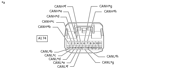
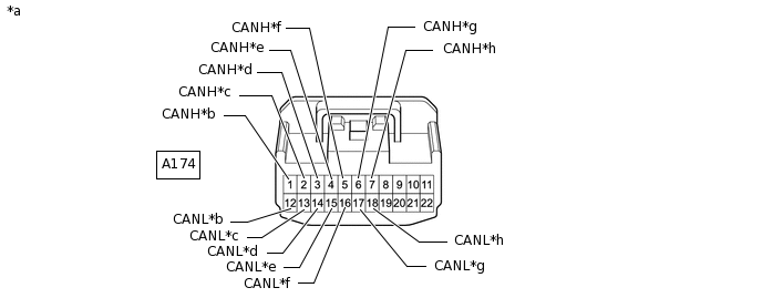
NO. 4 CAN JUNCTION CONNECTOR (for LHD except Sedan)
Check the No. 4 CAN junction connector.
Connection diagram
*a
Front view of wire harness connector
(to No. 4 CAN Junction Connector)
*b
to No. 3 CAN Junction Connector
*c
to DLC3
*d
to Main Body ECU (Multiplex Network Body ECU)
*e
to Headlight Swivel ECU Assembly
(w/ Automatic Headlight Beam Level Control System)
*f
to Brake Actuator Assembly
*g
to ECM
*h
to Clearance Warning ECU Assembly
(w/ Simple Intelligent Parking Assist System)
Check the connection diagram of the components which are connected to the No. 4 CAN junction connector.
Terminal No. (Symbol)
Wiring Color
Connected to
A174-1 (CANH)
L
No. 3 CAN junction connector
A174-12 (CANL)
W
A174-2 (CANH)
R
DLC3
A174-13 (CANL)
W
A174-3 (CANH)
G
Main body ECU (multiplex network body ECU)
A174-14 (CANL)
W
A174-4 (CANH)
Y
Headlight swivel ECU assembly*1
A174-15 (CANL)
W
A174-5 (CANH)
V
Brake actuator assembly
A174-16 (CANL)
W
A174-6 (CANH)
B
ECM
A174-17 (CANL)
W
A174-7 (CANH)
B
Clearance warning ECU assembly*2
A174-18 (CANL)
W
*1: w/ Automatic Headlight Beam Level Control System
*2: w/ Simple Intelligent Parking Assist System
NO. 1 CAN JUNCTION CONNECTOR (for RHD Sedan)
Check the No. 1 CAN junction connector.
Connection diagram
*a
Front view of wire harness connector
(to No. 1 CAN Junction Connector)
*b
to No. 3 CAN Junction Connector
*c
to Engine Stop and Start ECU
(w/ Stop and Start System)
*d
to Main Body ECU (Multiplex Network Body ECU)
*e
to Brake Actuator Assembly
*f
to ECM
Check the connection diagram of the components which are connected to the No. 1 CAN junction connector.
Terminal No. (Symbol)
Wiring Color
Connected to
A32-1 (CANH)
L
No. 3 CAN junction connector
A32-12 (CANL)
W
A32-2 (CANH)
P
Engine stop and start ECU*
A32-13 (CANL)
W
A32-3 (CANH)
G
Main body ECU (multiplex network body ECU)
A32-14 (CANL)
W
A32-5 (CANH)
V
Brake actuator assembly
A32-16 (CANL)
W
A32-6 (CANH)
B
ECM
A32-17 (CANL)
W
*: w/ Stop and Start System
NO. 3 CAN JUNCTION CONNECTOR (for RHD Sedan)
Check the No. 3 CAN junction connector.
Connection diagram
*a
Front view of wire harness connector
(to No. 3 CAN Junction Connector)
*b
to Airbag Sensor Assembly
*c
to Air Conditioning Amplifier Assembly
(w/ Air Conditioning System)
*d
to Radio and Display Receiver Assembly
(for Radio and Display Type)
*e
to Combination Meter Assembly
*f
to No. 1 CAN Junction Connector
*g
to Certification ECU (Smart Key ECU Assembly)
(w/ Entry and Start System)
*h
to Power Steering ECU Assembly
*i
to Steering Sensor (Spiral Cable with Sensor Sub-assembly)
*j
to DLC3
Check the connection diagram of the components which are connected to the No. 3 CAN junction connector.
Terminal No. (Symbol)
Wiring Color
Connected to
E57-1 (CANH)
V
Airbag sensor assembly
E57-12 (CANL)
W
E57-2 (CANH)
Y
Air conditioning amplifier assembly*1
E57-13 (CANL)
W
E57-3 (CANH)
Y
Radio and display receiver assembly*2
E57-14 (CANL)
W
E57-4 (CANH)
LG
Combination meter assembly
E57-15 (CANL)
W
E57-5 (CANH)
L
No. 1 CAN junction connector
E57-16 (CANL)
W
E57-6 (CANH)
R
Certification ECU (smart key ECU assembly)*3
E57-17 (CANL)
W
E57-9 (CANH)
GR
Power steering ECU assembly
E57-20 (CANL)
W
E57-10 (CANH)
SB
Steering sensor (spiral cable with sensor sub-assembly)
E57-21 (CANL)
W
E57-11 (CANH)
BE
DLC3
E57-22 (CANL)
W
*1: w/ Air Conditioning System
*2: for Radio and Display Type
*3: w/ Entry and Start System
NO. 3 CAN JUNCTION CONNECTOR (for RHD except Sedan)
Check the No. 3 CAN junction connector.
Connection diagram
*a
Front view of wire harness connector
(to No. 3 CAN Junction Connector)
*b
to Airbag Sensor Assembly
*c
to Air Conditioning Amplifier Assembly
(w/ Automatic Air Conditioning System)
*d
to Radio and Display Receiver Assembly
(for Radio and Display Type)
*e
to Combination Meter Assembly
*f
to No. 4 CAN Junction Connector
*g
to Certification ECU (Smart Key ECU Assembly)
(w/ Entry and Start System)
*h
to Pre-crash Safety City Sensor
(w/ Toyota Safety Sense)
*i
to Power Steering ECU Assembly
*j
to Steering Sensor (Spiral Cable with Sensor Sub-assembly)
*k
to DLC3
-
-
Check the connection diagram of the components which are connected to the No. 3 CAN junction connector.
Terminal No. (Symbol)
Wiring Color
Connected to
E57-1 (CANH)
V
Airbag sensor assembly
E57-12 (CANL)
W
E57-2 (CANH)
Y
Air conditioning amplifier assembly*1
E57-13 (CANL)
W
E57-3 (CANH)
G
Radio and display receiver assembly*2
E57-14 (CANL)
W
E57-4 (CANH)
LG
Combination meter assembly
E57-15 (CANL)
W
E57-5 (CANH)
L
No. 4 CAN junction connector
E57-16 (CANL)
W
E57-6 (CANH)
R
Certification ECU (smart key ECU assembly)*3
E57-17 (CANL)
W
E57-8 (CANH)
P
Pre-crash safety city sensor*4
E57-19 (CANL)
W
E57-9 (CANH)
GR
Power steering ECU assembly
E57-20 (CANL)
W
E57-10 (CANH)
SB
Steering sensor (spiral cable with sensor sub-assembly)
E57-21 (CANL)
W
E57-11 (CANH)
BE
DLC3
E57-22 (CANL)
W
*1: w/ Automatic Air Conditioning System
*2: for Radio and Display Type
*3: w/ Entry and Start System
*4: w/ Toyota Safety Sense
NO. 4 CAN JUNCTION CONNECTOR (for RHD except Sedan)
Check the No. 4 CAN junction connector.
Connection diagram
*a
Front view of wire harness connector
(to No. 4 CAN Junction Connector)
*b
to No. 3 CAN Junction Connector
*c
to Engine Stop and Start ECU
(w/ Stop and Start System)
*d
to Main Body ECU (Multiplex Network Body ECU)
*e
to Headlight Swivel ECU Assembly
(w/ Automatic Headlight Beam Level Control System)
*f
to Brake Actuator Assembly
*g
to ECM
*h
to Clearance Warning ECU Assembly
(w/ Simple Intelligent Parking Assist System)
Check the connection diagram of the components which are connected to the No. 4 CAN junction connector.
Terminal No. (Symbol)
Wiring Color
Connected to
A174-1 (CANH)
L
No. 3 CAN junction connector
A174-12 (CANL)
W
A174-2 (CANH)
P
Engine stop and start ECU*1
A174-13 (CANL)
W
A174-3 (CANH)
G
Main body ECU (multiplex network body ECU)
A174-14 (CANL)
W
A174-4 (CANH)
Y
Headlight swivel ECU assembly*2
A174-15 (CANL)
W
A174-5 (CANH)
V
Brake actuator assembly
A174-16 (CANL)
W
A174-6 (CANH)
B
ECM
A174-17 (CANL)
W
A174-7 (CANH)
B
Clearance warning ECU assembly*3
A174-18 (CANL)
W
*1: w/ Stop and Start System
*2: w/ Automatic Headlight Beam Level Control System
*3: w/ Simple Intelligent Parking Assist System
DLC3
Disconnect the cable from the negative (-) battery terminal.
-
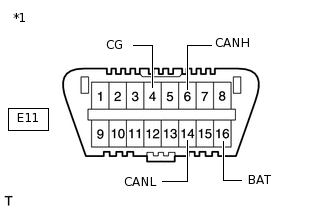
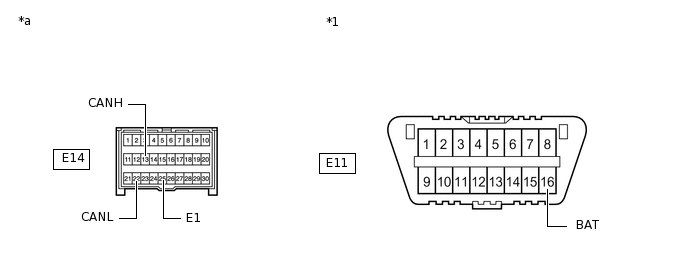
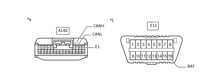
*1
DLC3
Measure the resistance according to the value(s) in the table below.
Standard Resistance
Terminal No. (Symbol)
Wiring Color
Terminal Description
Condition
Specified Condition
E11-6 (CANH) - E11-14 (CANL)
R- W*1
BE - W*2
HIGH-level CAN bus line - LOW-level CAN bus line
Cable disconnected from negative (-) battery terminal
54 to 69 Ω
E11-6 (CANH) - E11-4 (CG)
R - W-B*1
BE - W-B*2
HIGH-level CAN bus line - Ground
Cable disconnected from negative (-) battery terminal
200 Ω or higher
E11-14 (CANL) - E11-4 (CG)
W - W-B
LOW-level CAN bus line - Ground
Cable disconnected from negative (-) battery terminal
200 Ω or higher
E11-6 (CANH) - E11-16 (BAT)
R - G*1
BE - G*2
HIGH-level CAN bus line - Battery positive (+)
Cable disconnected from negative (-) battery terminal
6 kΩ or higher
E11-14 (CANL) - E11-16 (BAT)
W - G
LOW-level CAN bus line - Battery positive (+)
Cable disconnected from negative (-) battery terminal
6 kΩ or higher
*1: for LHD
*2: for RHD
ECM (for 1NR-FE)
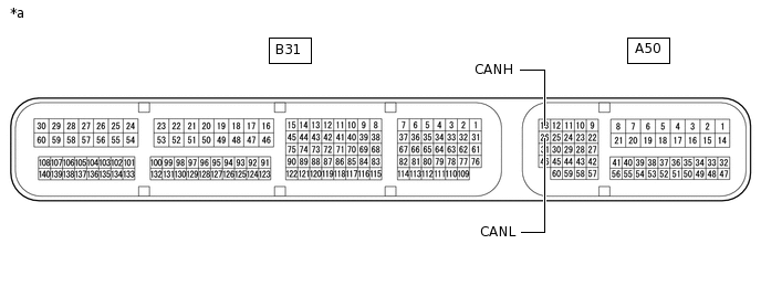
*a
Component without harness connected
(ECM)
-
-
Disconnect the cable from the negative (-) battery terminal.
Disconnect the A50 and B31 ECM connectors.
*a
Front view of wire harness connector
(to ECM)
-
-
Measure the resistance according to the value(s) in the table below.
Standard Resistance
Terminal No. (Symbol)
Wiring Color
Terminal Description
Condition
Specified Condition
A50-13 (CANH) - A50-26 (CANL)
B - W
HIGH-level CAN bus line - LOW-level CAN bus line
Cable disconnected from negative (-) battery terminal
108 to 132 Ω
A50-13 (CANH) - B31-16 (E1)
B - BR
HIGH-level CAN bus line - Ground
Cable disconnected from negative (-) battery terminal
200 Ω or higher
A50-26 (CANL) - B31-16 (E1)
W - BR
LOW-level CAN bus line - Ground
Cable disconnected from negative (-) battery terminal
200 Ω or higher
A50-13 (CANH) - A50-1 (BATT)
B - P
HIGH-level CAN bus line - Battery positive (+)
Cable disconnected from negative (-) battery terminal
6 kΩ or higher
A50-26 (CANL) - A50-1 (BATT)
W - P
LOW-level CAN bus line - Battery positive (+)
Cable disconnected from negative (-) battery terminal
6 kΩ or higher
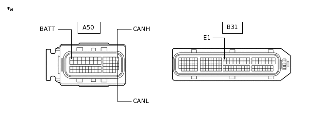
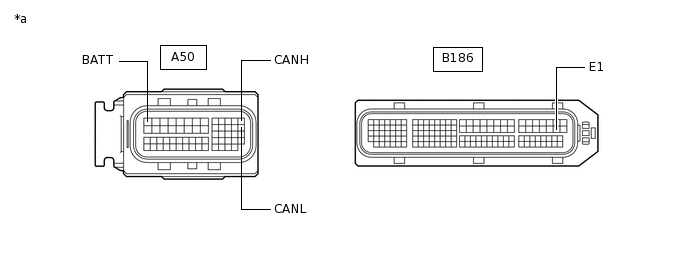
ECM (for 1ZR-FAE, 1ZR-FE or 2ZR-FE)
*a
Component without harness connected
(ECM)
-
-
Disconnect the cable from the negative (-) battery terminal.
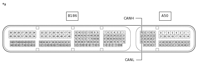
Disconnect the A50 and B186 ECM connectors.
*a
Front view of wire harness connector
(to ECM)
-
-
Measure the resistance according to the value(s) in the table below.
Standard Resistance
Terminal No. (Symbol)
Wiring Color
Terminal Description
Condition
Specified Condition
A50-13 (CANH) - A50-26 (CANL)
B - W
HIGH-level CAN bus line - LOW-level CAN bus line
Cable disconnected from negative (-) battery terminal
108 to 132 Ω
A50-13 (CANH) - B186-59 (E1)
B - BR
HIGH-level CAN bus line - Ground
Cable disconnected from negative (-) battery terminal
200 Ω or higher
A50-26 (CANL) - B186-59 (E1)
W - BR
LOW-level CAN bus line - Ground
Cable disconnected from negative (-) battery terminal
200 Ω or higher
A50-13 (CANH) - A50-1 (BATT)
B - P
HIGH-level CAN bus line - Battery positive (+)
Cable disconnected from negative (-) battery terminal
6 kΩ or higher
A50-26 (CANL) - A50-1 (BATT)
W - P
LOW-level CAN bus line - Battery positive (+)
Cable disconnected from negative (-) battery terminal
6 kΩ or higher
ECM (for 1ND-TV with Glow Plug Controller)
*a
Component without harness connected
(ECM)
-
-
Disconnect the cable from the negative (-) battery terminal.
-
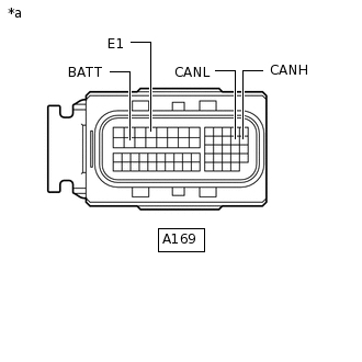
*a
Front view of wire harness connector
(to ECM)
Disconnect the A169 ECM connector.
Measure the resistance according to the value(s) in the table below.
Standard Resistance
Terminal No. (Symbol)
Wiring Color
Terminal Description
Condition
Specified Condition
A169-26 (CANH) - A169-25 (CANL)
B - W
HIGH-level CAN bus line - LOW-level CAN bus line
Cable disconnected from negative (-) battery terminal
108 to 132 Ω
A169-26 (CANH) - A169-4 (E1)
B - W-B
HIGH-level CAN bus line - Ground
Cable disconnected from negative (-) battery terminal
200 Ω or higher
A169-25 (CANL) - A169-4 (E1)
W - W-B
LOW-level CAN bus line - Ground
Cable disconnected from negative (-) battery terminal
200 Ω or higher
A169-26 (CANH) - A169-15 (BATT)
B - W
HIGH-level CAN bus line - Battery positive (+)
Cable disconnected from negative (-) battery terminal
6 kΩ or higher
A169-25 (CANL) - A169-15 (BATT)
W - W
LOW-level CAN bus line - Battery positive (+)
Cable disconnected from negative (-) battery terminal
6 kΩ or higher
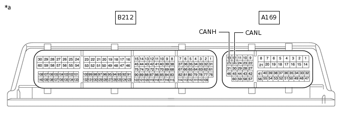
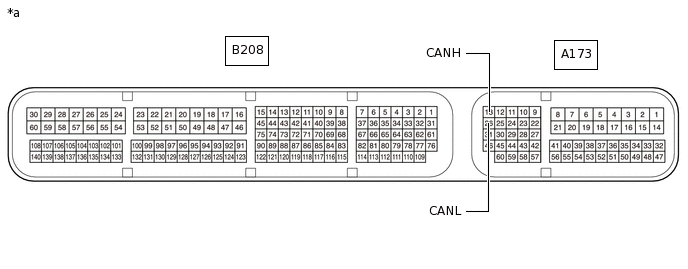
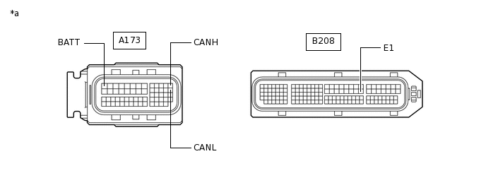
ECM (for 8NR-FTS)
*a
Component without harness connected
(ECM)
-
-
Disconnect the cable from the negative (-) battery terminal.
Disconnect the A173 and B208 ECM connectors.
*a
Front view of wire harness connector
(to ECM)
-
-
Measure the resistance according to the value(s) in the table below.
Standard Resistance
Terminal No. (Symbol)
Wiring Color
Terminal Description
Condition
Specified Condition
A173-13 (CANH) - A173-26 (CANL)
B - W
HIGH-level CAN bus line - LOW-level CAN bus line
Cable disconnected from negative (-) battery terminal
108 to 132 Ω
A173-13 (CANH) - B208-53 (E1)
B - W-B
HIGH-level CAN bus line - Ground
Cable disconnected from negative (-) battery terminal
200 Ω or higher
A173-26 (CANL) - B208-53 (E1)
W - W-B
LOW-level CAN bus line - Ground
Cable disconnected from negative (-) battery terminal
200 Ω or higher
A173-13 (CANH) - A173-1 (BATT)
B - B
HIGH-level CAN bus line - Battery positive (+)
Cable disconnected from negative (-) battery terminal
6 kΩ or higher
A173-26 (CANL) - A173-1 (BATT)
W - B
LOW-level CAN bus line - Battery positive (+)
Cable disconnected from negative (-) battery terminal
6 kΩ or higher
-

*a
Component without harness connected
(ECM)
-
-
ECM (for 1WW)
Disconnect the cable from the negative (-) battery terminal.
-
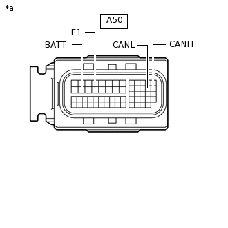
*a
Front view of wire harness connector
(to ECM)
Disconnect the A50 ECM connector.
Measure the resistance according to the value(s) in the table below.
Standard Resistance
Terminal No. (Symbol)
Wiring Color
Terminal Description
Condition
Specified Condition
A50-26 (CANH) - A50-25 (CANL)
B - W
HIGH-level CAN bus line - LOW-level CAN bus line
Cable disconnected from negative (-) battery terminal
108 to 132 Ω
A50-26 (CANH) - A50-4 (E1)
B - W-B
HIGH-level CAN bus line - Ground
Cable disconnected from negative (-) battery terminal
200 Ω or higher
A50-25 (CANL) - A50-4 (E1)
W - W-B
LOW-level CAN bus line - Ground
Cable disconnected from negative (-) battery terminal
200 Ω or higher
A50-26 (CANH) - A50-15 (BATT)
B - B
HIGH-level CAN bus line - Battery positive (+)
Cable disconnected from negative (-) battery terminal
6 kΩ or higher
A50-25 (CANL) - A50-15 (BATT)
W - B
LOW-level CAN bus line - Battery positive (+)
Cable disconnected from negative (-) battery terminal
6 kΩ or higher
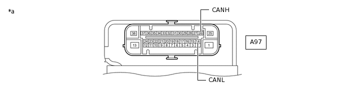
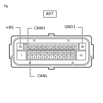
BRAKE ACTUATOR ASSEMBLY (w/ VSC)
*a
Component without harness connected
(Brake Actuator Assembly)
-
-
Disconnect the cable from the negative (-) battery terminal.
-
*a
Front view of wire harness connector
(to Brake Actuator Assembly)
Disconnect the A97 brake actuator assembly connector.
Measure the resistance according to the value(s) in the table below.
Standard Resistance
Terminal No. (Symbol)
Wiring Color
Terminal Description
Condition
Specified Condition
A97-26 (CANH) - A97-14 (CANL)
V - W
HIGH-level CAN bus line - LOW-level CAN bus line
Cable disconnected from negative (-) battery terminal
54 to 69 Ω
A97-26 (CANH) - A97-38 (GND1)
V - W-B
HIGH-level CAN bus line - Ground
Cable disconnected from negative (-) battery terminal
200 Ω or higher
A97-14 (CANL) - A97-38 (GND1)
W - W-B
LOW-level CAN bus line - Ground
Cable disconnected from negative (-) battery terminal
200 Ω or higher
A97-26 (CANH) - A97-25 (+BS)
V - W
HIGH-level CAN bus line - Battery positive (+)
Cable disconnected from negative (-) battery terminal
6 kΩ or higher
A97-14 (CANL) - A97-25 (+BS)
W - W
LOW-level CAN bus line - Battery positive (+)
Cable disconnected from negative (-) battery terminal
6 kΩ or higher
BRAKE ACTUATOR ASSEMBLY (w/o VSC)

*a
Component without harness connected
(Brake Actuator Assembly)
-
-
Disconnect the cable from the negative (-) battery terminal.
-

*a
Front view of wire harness connector
(to Brake Actuator Assembly)
Disconnect the A120 brake actuator assembly connector.
Measure the resistance according to the value(s) in the table below.
Standard Resistance
Terminal No. (Symbol)
Wiring Color
Terminal Description
Condition
Specified Condition
A120-26 (CANH) - A120-14 (CANL)
V - W
HIGH-level CAN bus line - LOW-level CAN bus line
Cable disconnected from negative (-) battery terminal
54 to 69 Ω
A120-26 (CANH) - A120-38 (GND1)
V - W-B
HIGH-level CAN bus line - Ground
Cable disconnected from negative (-) battery terminal
200 Ω or higher
A120-14 (CANL) - A120-38 (GND1)
W - W-B
LOW-level CAN bus line - Ground
Cable disconnected from negative (-) battery terminal
200 Ω or higher
A120-26 (CANH) - A120-25 (+BS)
V - W
HIGH-level CAN bus line - Battery positive (+)
Cable disconnected from negative (-) battery terminal
6 kΩ or higher
A120-14 (CANL) - A120-25 (+BS)
W - W
LOW-level CAN bus line - Battery positive (+)
Cable disconnected from negative (-) battery terminal
6 kΩ or higher
AIRBAG SENSOR ASSEMBLY
*a
Component without harness connected
(Airbag Sensor Assembly)
-
-
Disconnect the cable from the negative (-) battery terminal.
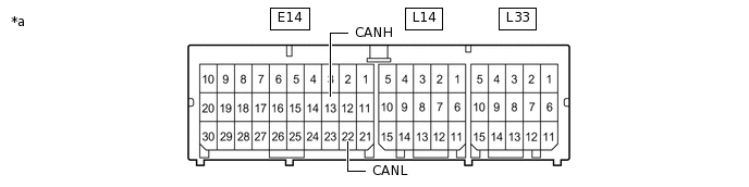
Disconnect the E14 airbag sensor assembly connector.
*1
DLC3
-
-
*a
Front view of wire harness connector
(to Airbag Sensor Assembly)
-
-
Measure the resistance according to the value(s) in the table below.
Standard Resistance
Terminal No. (Symbol)
Wiring Color
Terminal Description
Condition
Specified Condition
E14-13 (CANH) - E14-22 (CANL)
V - W
HIGH-level CAN bus line - LOW-level CAN bus line
Cable disconnected from negative (-) battery terminal
54 to 69 Ω
E14-13 (CANH) - E14-25 (E1)
V - W-B
HIGH-level CAN bus line - Ground
Cable disconnected from negative (-) battery terminal
200 Ω or higher
E14-22 (CANL) - E14-25 (E1)
W - W-B
LOW-level CAN bus line - Ground
Cable disconnected from negative (-) battery terminal
200 Ω or higher
E14-13 (CANH) - E11-16 (BAT)
V - G
HIGH-level CAN bus line - Battery positive (+)
Cable disconnected from negative (-) battery terminal
6 kΩ or higher
E14-22 (CANL) - E11-16 (BAT)
W - G
LOW-level CAN bus line - Battery positive (+)
Cable disconnected from negative (-) battery terminal
6 kΩ or higher
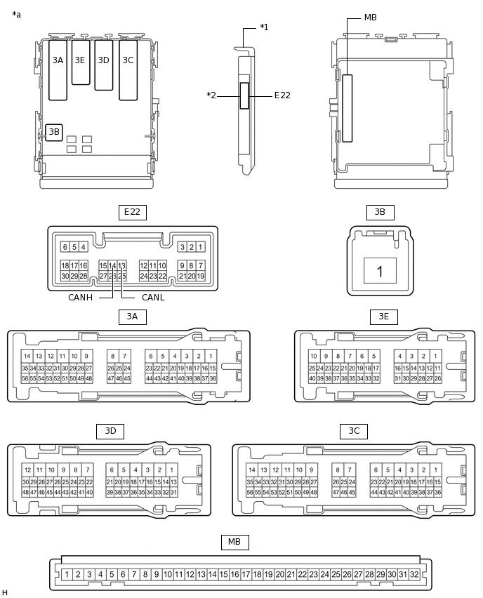
INSTRUMENT PANEL JUNCTION BLOCK ASSEMBLY AND MAIN BODY ECU (MULTIPLEX NETWORK BODY ECU)
*1
Main Body ECU (Multiplex Network Body ECU)
*2
1 Connector
*a
Component without harness connected
(Instrument Panel Junction Block Assembly and Main Body ECU (Multiplex Network Body ECU))
-
-
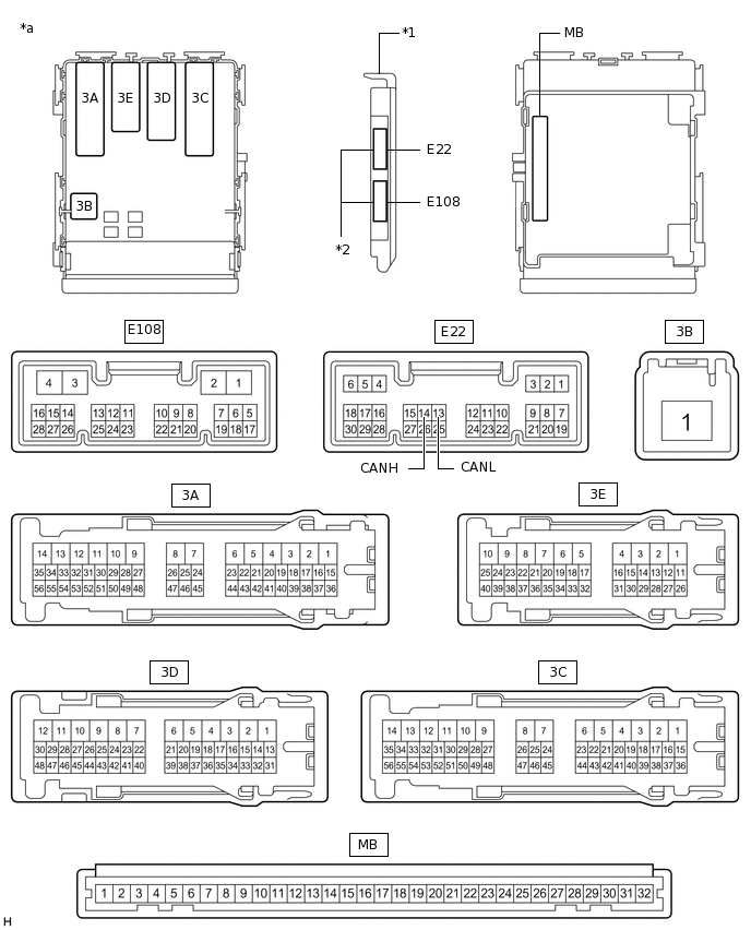
*1
Main Body ECU (Multiplex Network Body ECU)
*2
2 Connectors
*a
Component without harness connected
(Instrument Panel Junction Block Assembly and Main Body ECU (Multiplex Network Body ECU))
-
-
Disconnect the cable from the negative (-) battery terminal.
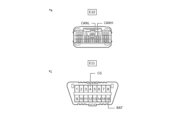
Disconnect the E22 main body ECU (multiplex network body ECU) connector.
*1
DLC3
-
-
*a
Front view of wire harness connector
(to Main Body ECU (Multiplex Network Body ECU))
-
-
Measure the resistance according to the value(s) in the table below.
Standard Resistance
Terminal No. (Symbol)
Wiring Color
Terminal Description
Condition
Specified Condition
E22-14 (CANH) - E22-13 (CANL)
G - W
HIGH-level CAN bus line - LOW-level CAN bus line
Cable disconnected from negative (-) battery terminal
54 to 69 Ω
E22-14 (CANH) - E11-4 (CG)
G - W-B
HIGH-level CAN bus line - Ground
Cable disconnected from negative (-) battery terminal
200 Ω or higher
E22-13 (CANL) - E11-4 (CG)
W - W-B
LOW-level CAN bus line - Ground
Cable disconnected from negative (-) battery terminal
200 Ω or higher
E22-14 (CANH) - E11-16 (BAT)
G - G
HIGH-level CAN bus line - Battery positive (+)
Cable disconnected from negative (-) battery terminal
6 kΩ or higher
E22-13 (CANL) - E11-16 (BAT)
W - G
LOW-level CAN bus line - Battery positive (+)
Cable disconnected from negative (-) battery terminal
6 kΩ or higher
STEERING SENSOR (SPIRAL CABLE WITH SENSOR SUB-ASSEMBLY) (w/ VSC)
Disconnect the cable from the negative (-) battery terminal.
-
*a
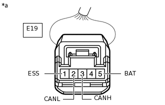
Front view of wire harness connector
(to Steering Sensor (Spiral Cable with Sensor Sub-assembly))
Disconnect the E19 steering sensor (spiral cable with sensor sub-assembly) connector.
Measure the resistance according to the value(s) in the table below.
Standard Resistance
Terminal No. (Symbol)
Wiring Color
Terminal Description
Condition
Specified Condition
E19-3 (CANH) - E19-2 (CANL)
SB - W
HIGH-level CAN bus line - LOW-level CAN bus line
Cable disconnected from negative (-) battery terminal
54 to 69 Ω
E19-3 (CANH) - E19-1 (ESS)
SB - BR
HIGH-level CAN bus line - Ground
Cable disconnected from negative (-) battery terminal
200 Ω or higher
E19-2 (CANL) - E19-1 (ESS)
W - BR
LOW-level CAN bus line - Ground
Cable disconnected from negative (-) battery terminal
200 Ω or higher
E19-3 (CANH) - E19-5 (BAT)
SB - W
HIGH-level CAN bus line - Battery positive (+)
Cable disconnected from negative (-) battery terminal
6 kΩ or higher
E19-2 (CANL) - E19-5 (BAT)
W - W
LOW-level CAN bus line - Battery positive (+)
Cable disconnected from negative (-) battery terminal
6 kΩ or higher
POWER STEERING ECU ASSEMBLY
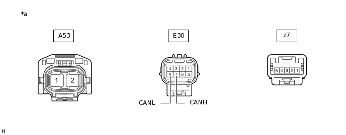
*a
Component without harness connected
(Power Steering ECU Assembly)
-
-
Disconnect the cable from the negative (-) battery terminal.
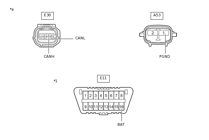
Disconnect the A53 and E30 power steering ECU assembly connectors.
*1
DLC3
-
-
*a
Front view of wire harness connector
(to Power Steering ECU Assembly)
-
-
Measure the resistance according to the value(s) in the table below.
Standard Resistance
Terminal No. (Symbol)
Wiring Color
Terminal Description
Condition
Specified Condition
E30-7 (CANH) - E30-8 (CANL)
GR - W
HIGH-level CAN bus line - LOW-level CAN bus line
Cable disconnected from negative (-) battery terminal
54 to 69 Ω
E30-7 (CANH) - A53-1 (PGND)
GR- W-B
HIGH-level CAN bus line - Ground
Cable disconnected from negative (-) battery terminal
200 Ω or higher
E30-8 (CANL) - A53-1 (PGND)
W - W-B
LOW-level CAN bus line - Ground
Cable disconnected from negative (-) battery terminal
200 Ω or higher
E30-7 (CANH) - E11-16 (BAT)
GR - G
HIGH-level CAN bus line - Battery positive (+)
Cable disconnected from negative (-) battery terminal
6 kΩ or higher
E30-8 (CANL) - E11-16 (BAT)
W - G
LOW-level CAN bus line - Battery positive (+)
Cable disconnected from negative (-) battery terminal
6 kΩ or higher
CERTIFICATION ECU (SMART KEY ECU ASSEMBLY) (w/ Entry and Start System)
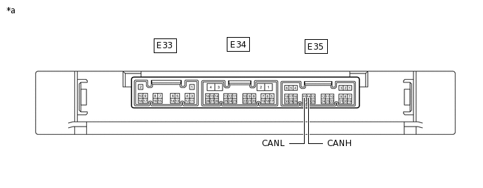
*a
Component without harness connected
(Certification ECU (Smart Key ECU Assembly))
-
-
Disconnect the cable from the negative (-) battery terminal.
-
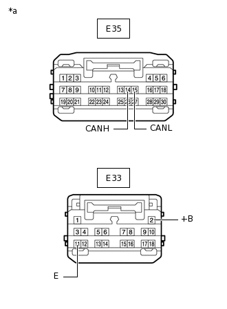
*a
Front view of wire harness connector
(to Certification ECU (Smart Key ECU Assembly))
Disconnect the E33 and E35 certification ECU (smart key ECU assembly) connectors.
Measure the resistance according to the value(s) in the table below.
Standard Resistance
Terminal No. (Symbol)
Wiring Color
Terminal Description
Condition
Specified Condition
E35-14 (CANH) - E35-15 (CANL)
R - W
HIGH-level CAN bus line - LOW-level CAN bus line
Cable disconnected from negative (-) battery terminal
54 to 69 Ω
E35-14 (CANH) - E33-11 (E)
R- W-B
HIGH-level CAN bus line - Ground
Cable disconnected from negative (-) battery terminal
200 Ω or higher
E35-15 (CANL) - E33-11 (E)
W - W-B
LOW-level CAN bus line - Ground
Cable disconnected from negative (-) battery terminal
200 Ω or higher
E35-14 (CANH) - E33-2 (+B)
R - L
HIGH-level CAN bus line - Battery positive (+)
Cable disconnected from negative (-) battery terminal
6 kΩ or higher
E35-15 (CANL) - E33-2 (+B)
W - L
LOW-level CAN bus line - Battery positive (+)
Cable disconnected from negative (-) battery terminal
6 kΩ or higher
COMBINATION METER ASSEMBLY
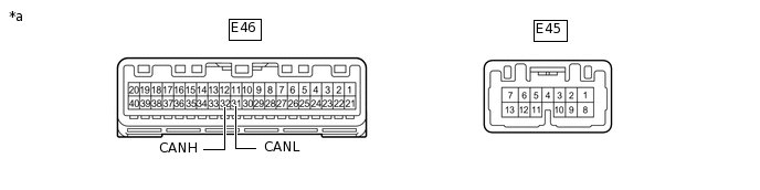
*a
Component without harness connected
(Combination Meter Assembly)
-
-
Disconnect the cable from the negative (-) battery terminal.
-
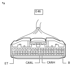
*a
Front view of wire harness connector
(to Combination Meter Assembly)
Disconnect the E46 combination meter assembly connector.
Measure the resistance according to the value(s) in the table below.
Standard Resistance
Terminal No. (Symbol)
Wiring Color
Terminal Description
Condition
Specified Condition
E46-32 (CANH) - E46-31 (CANL)
LG - W
HIGH-level CAN bus line - LOW-level CAN bus line
Cable disconnected from negative (-) battery terminal
108 to 132 Ω
E46-32 (CANH) - E46-21 (ET)
LG - BR
HIGH-level CAN bus line - Ground
Cable disconnected from negative (-) battery terminal
200 Ω or higher
E46-31 (CANL) - E46-21 (ET)
W - BR
LOW-level CAN bus line - Ground
Cable disconnected from negative (-) battery terminal
200 Ω or higher
E46-32 (CANH) - E46-40 (B)
LG - W
HIGH-level CAN bus line - Battery positive (+)
Cable disconnected from negative (-) battery terminal
6 kΩ or higher
E46-31 (CANL) - E46-40 (B)
W - W
LOW-level CAN bus line - Battery positive (+)
Cable disconnected from negative (-) battery terminal
6 kΩ or higher
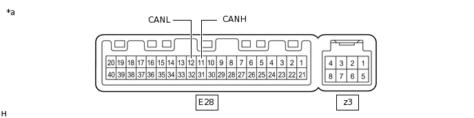
AIR CONDITIONING AMPLIFIER ASSEMBLY (w/ Automatic Air Conditioning System)
*a
Component without harness connected
(Air Conditioning Amplifier Assembly)
-
-
Disconnect the cable from the negative (-) battery terminal.
-
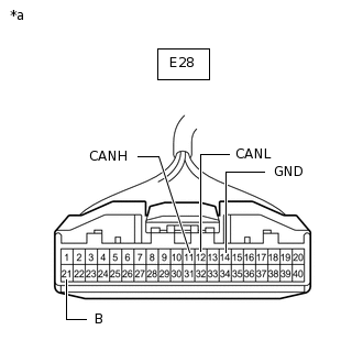
*a
Front view of wire harness connector
(to Air Conditioning Amplifier Assembly)
Disconnect the E28 air conditioning amplifier assembly connector.
Measure the resistance according to the value(s) in the table below.
Standard Resistance
Terminal No. (Symbol)
Wiring Color
Terminal Description
Condition
Specified Condition
E28-11 (CANH) - E28-12 (CANL)
Y - W
HIGH-level CAN bus line - LOW-level CAN bus line
Cable disconnected from negative (-) battery terminal
54 to 69 Ω
E28-11 (CANH) - E28-14 (GND)
Y - BR
HIGH-level CAN bus line - Ground
Cable disconnected from negative (-) battery terminal
200 Ω or higher
E28-12 (CANL) - E28-14 (GND)
W - BR
LOW-level CAN bus line - Ground
Cable disconnected from negative (-) battery terminal
200 Ω or higher
E28-11 (CANH) - E28-21 (B)
Y - W
HIGH-level CAN bus line - Battery positive (+)
Cable disconnected from negative (-) battery terminal
6 kΩ or higher
E28-12 (CANL) - E28-21 (B)
W - W
LOW-level CAN bus line - Battery positive (+)
Cable disconnected from negative (-) battery terminal
6 kΩ or higher
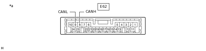
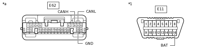
AIR CONDITIONING AMPLIFIER ASSEMBLY (w/Manual Air Conditioning System)
*a
Component without harness connected
(Air Conditioning Amplifier Assembly)
-
-
Disconnect the cable from the negative (-) battery terminal.
Disconnect the E62 air conditioning amplifier assembly connector.
*1
DLC3
-
-
*a
Front view of wire harness connector
(to Air Conditioning Amplifier Assembly)
-
-
Measure the resistance according to the value(s) in the table below.
Standard Resistance
Terminal No. (Symbol)
Wiring Color
Terminal Description
Condition
Specified Condition
E62-8 (CANH) - E62-9 (CANL)
Y - W
HIGH-level CAN bus line - LOW-level CAN bus line
Cable disconnected from negative (-) battery terminal
54 to 69 Ω
E62-8 (CANH) - E62-23 (GND)
Y - BR
HIGH-level CAN bus line - Ground
Cable disconnected from negative (-) battery terminal
200 Ω or higher
E62-9 (CANL) - E62-23 (GND)
W - BR
LOW-level CAN bus line - Ground
Cable disconnected from negative (-) battery terminal
200 Ω or higher
E62-8 (CANH) - E11-16 (BAT)
Y - G
HIGH-level CAN bus line - Battery positive (+)
Cable disconnected from negative (-) battery terminal
6 kΩ or higher
E62-9 (CANL) - E11-16 (BAT)
W - G
LOW-level CAN bus line - Battery positive (+)
Cable disconnected from negative (-) battery terminal
6 kΩ or higher
-
*a
Component without harness connected
(Radio and Display Receiver Assembly)
-
-
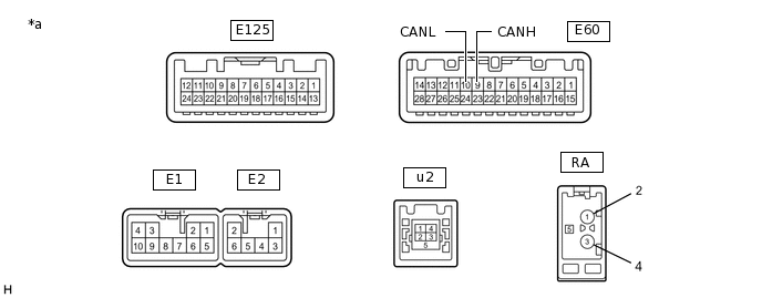
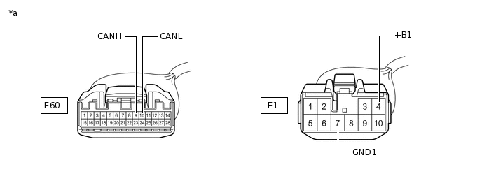
RADIO AND DISPLAY RECEIVER ASSEMBLY (for Radio and Display Type without Navigation System)
Disconnect the cable from the negative (-) battery terminal.
Disconnect the E1 and E60 radio and display receiver assembly connectors.
*a
Front view of wire harness connector
(to Radio and Display Receiver Assembly)
-
-
Measure the resistance according to the value(s) in the table below.
Standard Resistance
Terminal No. (Symbol)
Wiring Color
Terminal Description
Condition
Specified Condition
E60-9 (CANH) - E60-10 (CANL)
G - W*1
Y - W*2
HIGH-level CAN bus line - LOW-level CAN bus line
Cable disconnected from negative (-) battery terminal
54 to 69 Ω
E60-9 (CANH) - E1-7 (GND1)
G - BR*1
Y - BR*2
HIGH-level CAN bus line - Ground
Cable disconnected from negative (-) battery terminal
200 Ω or higher
E60-10 (CANL) - E1-7 (GND1)
W - BR
LOW-level CAN bus line - Ground
Cable disconnected from negative (-) battery terminal
200 Ω or higher
E60-9 (CANH) - E1-4 (+B1)
G - SB*1
Y - SB*2
HIGH-level CAN bus line - Battery positive (+)
Cable disconnected from negative (-) battery terminal
6 kΩ or higher
E60-10 (CANL) - E1-4 (+B1)
W - SB
LOW-level CAN bus line - Battery positive (+)
Cable disconnected from negative (-) battery terminal
6 kΩ or higher
*1: except Sedan
*2: for Sedan
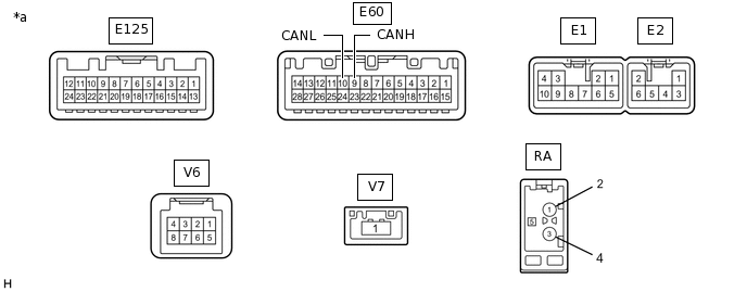
RADIO AND DISPLAY RECEIVER ASSEMBLY (for Radio and Display Type with Navigation System)
*a
Component without harness connected
(Radio and Display Receiver Assembly)
-
-
Disconnect the cable from the negative (-) battery terminal.
Disconnect the E1 and E60 radio and display receiver assembly connectors.

*a
Front view of wire harness connector
(to Radio and Display Receiver Assembly)
-
-
Measure the resistance according to the value(s) in the table below.
Standard Resistance
Terminal No. (Symbol)
Wiring Color
Terminal Description
Condition
Specified Condition
E60-9 (CANH) - E60-10 (CANL)
G - W*1
Y - W*2
HIGH-level CAN bus line - LOW-level CAN bus line
Cable disconnected from negative (-) battery terminal
54 to 69 Ω
E60-9 (CANH) - E1-7 (GND1)
G - BR*1
Y - BR*2
HIGH-level CAN bus line - Ground
Cable disconnected from negative (-) battery terminal
200 Ω or higher
E60-10 (CANL) - E1-7 (GND1)
W - BR
LOW-level CAN bus line - Ground
Cable disconnected from negative (-) battery terminal
200 Ω or higher
E60-9 (CANH) - E1-4 (+B1)
G - SB*1
Y - SB*2
HIGH-level CAN bus line - Battery positive (+)
Cable disconnected from negative (-) battery terminal
6 kΩ or higher
E60-10 (CANL) - E1-4 (+B1)
W - SB
LOW-level CAN bus line - Battery positive (+)
Cable disconnected from negative (-) battery terminal
6 kΩ or higher
*1: except Sedan
*2: for Sedan
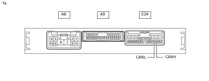
ENGINE STOP AND START ECU (w/ Stop and Start System)
*a
Component without harness connected
(Engine Stop and Start ECU)
-
-
Disconnect the cable from the negative (-) battery terminal.
-
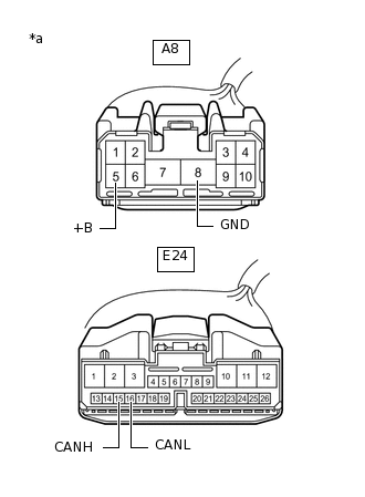
*a
Front view of wire harness connector
(to Engine Stop and Start ECU)
Disconnect the A8 and E24 engine stop and start ECU connectors.
Measure the resistance according to the value(s) in the table below.
Standard Resistance
Terminal No. (Symbol)
Wiring Color
Terminal Description
Condition
Specified Condition
E24-15 (CANH) - E24-16 (CANL)
P - W
HIGH-level CAN bus line - LOW-level CAN bus line
Cable disconnected from negative (-) battery terminal
54 to 69 Ω
E24-15 (CANH) - A8-8 (GND)
P - W-B
HIGH-level CAN bus line - Ground
Cable disconnected from negative (-) battery terminal
200 Ω or higher
E24-16 (CANL) - A8-8 (GND)
W - W-B
LOW-level CAN bus line - Ground
Cable disconnected from negative (-) battery terminal
200 Ω or higher
E24-15 (CANH) - A8-5 (+B)
P - B
HIGH-level CAN bus line - Battery positive (+)
Cable disconnected from negative (-) battery terminal
6 kΩ or higher
E24-16 (CANL) - A8-5 (+B)
W - B
LOW-level CAN bus line - Battery positive (+)
Cable disconnected from negative (-) battery terminal
6 kΩ or higher
HEADLIGHT LEVELING ECU ASSEMBLY (for Sedan with Automatic Headlight Beam Level Control System)
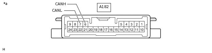
*a
Component without harness connected
(Headlight Leveling ECU Assembly)
-
-
Disconnect the cable from the negative (-) battery terminal.
Disconnect the A182 headlight leveling ECU assembly connector.
*1
DLC3
-
-
*a
Front view of wire harness connector
(to Headlight Leveling ECU Assembly)
-
-
Measure the resistance according to the value(s) in the table below.
Standard Resistance
Terminal No. (Symbol)
Wiring Color
Terminal Description
Condition
Specified Condition
A182-6 (CANH) - A182-7 (CANL)
Y - W
HIGH-level CAN bus line - LOW-level CAN bus line
Cable disconnected from negative (-) battery terminal
54 to 69 Ω
A182-6 (CANH) - A182-9 (E1)
Y - W-B
HIGH-level CAN bus line - Ground
Cable disconnected from negative (-) battery terminal
200 Ω or higher
A182-7 (CANL) - A182-9 (E1)
W - W-B
LOW-level CAN bus line - Ground
Cable disconnected from negative (-) battery terminal
200 Ω or higher
A182-6 (CANH) - E11-16 (BAT)
Y - G
HIGH-level CAN bus line - Battery positive (+)
Cable disconnected from negative (-) battery terminal
6 kΩ or higher
A182-7 (CANL) - E11-16 (BAT)
W - G
LOW-level CAN bus line - Battery positive (+)
Cable disconnected from negative (-) battery terminal
6 kΩ or higher
HEADLIGHT SWIVEL ECU ASSEMBLY (except Sedan with Automatic Headlight Beam Level Control System)
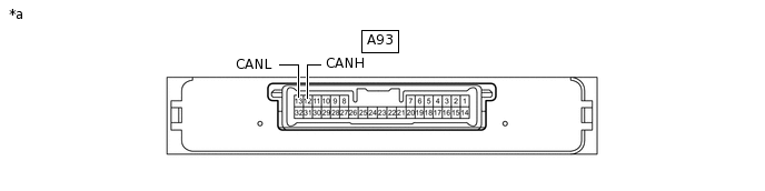
*a
Component without harness connected
(Headlight Swivel ECU Assembly)
-
-
Disconnect the cable from the negative (-) battery terminal.
-
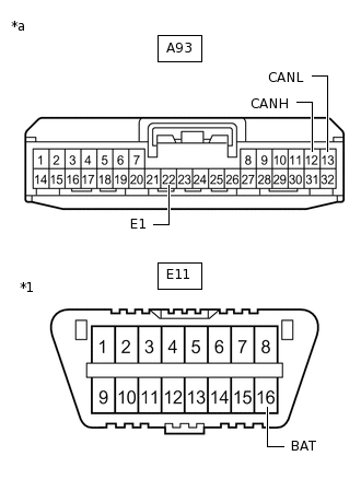
*1
DLC3
*a
Front view of wire harness connector
(to Headlight Swivel ECU Assembly)
Disconnect the A93 headlight swivel ECU assembly connector.
Measure the resistance according to the value(s) in the table below.
Standard Resistance
Terminal No. (Symbol)
Wiring Color
Terminal Description
Condition
Specified Condition
A93-12 (CANH) - A93-13 (CANL)
Y - W
HIGH-level CAN bus line - LOW-level CAN bus line
Cable disconnected from negative (-) battery terminal
54 to 69 Ω
A93-12 (CANH) - A93-22 (E1)
Y - W-B
HIGH-level CAN bus line - Ground
Cable disconnected from negative (-) battery terminal
200 Ω or higher
A93-13 (CANL) - A93-22 (E1)
W - W-B
LOW-level CAN bus line - Ground
Cable disconnected from negative (-) battery terminal
200 Ω or higher
A93-12 (CANH) - E11-16 (BAT)
Y - G
HIGH-level CAN bus line - Battery positive (+)
Cable disconnected from negative (-) battery terminal
6 kΩ or higher
A93-13 (CANL) - E11-16 (BAT)
W - G
LOW-level CAN bus line - Battery positive (+)
Cable disconnected from negative (-) battery terminal
6 kΩ or higher
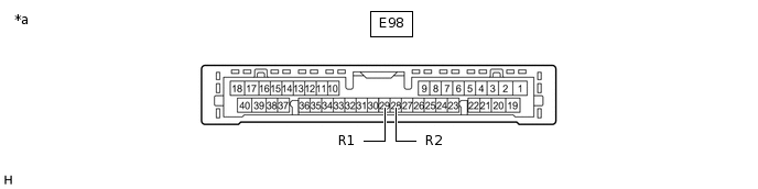
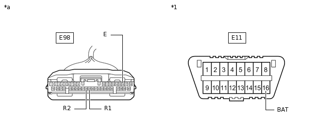
CLEARANCE WARNING ECU ASSEMBLY (w/ Simple Intelligent Parking Assist System)
*a
Component without harness connected
(Clearance Warning ECU Assembly)
-
-
Disconnect the cable from the negative (-) battery terminal.
Disconnect the E98 clearance warning ECU assembly connector.
*1
DLC3
-
-
*a
Front view of wire harness connector
(to Clearance Warning ECU Assembly)
-
-
Measure the resistance according to the value(s) in the table below.
Standard Resistance
Terminal No. (Symbol)
Wiring Color
Terminal Description
Condition
Specified Condition
E98-29 (R1) - E98-28 (R2)
B - W
HIGH-level CAN bus line - LOW-level CAN bus line
Cable disconnected from negative (-) battery terminal
54 to 69 Ω
E98-29 (R1) - E98-16 (E)
B - BR
HIGH-level CAN bus line - Ground
Cable disconnected from negative (-) battery terminal
200 Ω or higher
E98-28 (R2) - E98-16 (E)
W - BR
LOW-level CAN bus line - Ground
Cable disconnected from negative (-) battery terminal
200 Ω or higher
E98-29 (R1) - E11-16 (BAT)
B - G
HIGH-level CAN bus line - Battery positive (+)
Cable disconnected from negative (-) battery terminal
6 kΩ or higher
E98-28 (R2) - E11-16 (BAT)
W - G
LOW-level CAN bus line - Battery positive (+)
Cable disconnected from negative (-) battery terminal
6 kΩ or higher
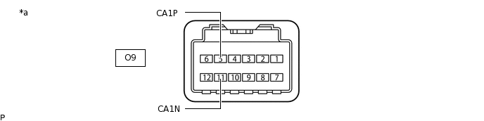
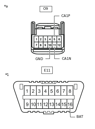
PRE-CRASH SAFETY CITY SENSOR (w/ Toyota Safety Sense)
*a
Component without harness connected
(Pre-crash Safety City Sensor)
-
-
Disconnect the cable from the negative (-) battery terminal.
-
*1
DLC3
*a
Front view of wire harness connector
(to Pre-crash Safety City Sensor)
Disconnect the O9 pre-crash safety city sensor connector.
Measure the resistance according to the value(s) in the table below.
Standard Resistance
Terminal No. (Symbol)
Wiring Color
Terminal Description
Condition
Specified Condition
O9-5 (CA1P) - O9-11 (CA1N)
P - W
HIGH-level CAN bus line - LOW-level CAN bus line
Cable disconnected from negative (-) battery terminal
54 to 69 Ω
O9-5 (CA1P) - O9-10 (GND)
P - W-B
HIGH-level CAN bus line - Ground
Cable disconnected from negative (-) battery terminal
200 Ω or higher
O9-11 (CA1N) - O9-10 (GND)
W - W-B
LOW-level CAN bus line - Ground
Cable disconnected from negative (-) battery terminal
200 Ω or higher
O9-5 (CA1P) - E11-16 (BAT)
P - G
HIGH-level CAN bus line - Battery positive (+)
Cable disconnected from negative (-) battery terminal
6 kΩ or higher
O9-11 (CA1N) - E11-16 (BAT)
W - G
LOW-level CAN bus line - Battery positive (+)
Cable disconnected from negative (-) battery terminal
6 kΩ or higher
TELEMATICS TRANSCEIVER (w/ Manual (SOS) Switch)
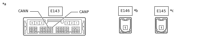
*a
Component without harness connected
(Telematics Transceiver)
*b
Connector Color: Blue (to Telephone Antenna)
*c
Connector Color: Gray (to GNSS Antenna)
-
-
Disconnect the cable from the negative (-) battery terminal.
-
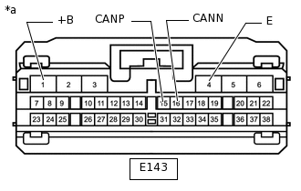
*a
Front view of wire harness connector
(to Telematics Transceiver)
Disconnect the E143 telematics transceiver connector.
Measure the resistance according to the value(s) in the table below.
Standard Resistance
Terminal No. (Symbol)
Wiring Color
Terminal Description
Condition
Specified Condition
E143-15 (CANP) - E143-16 (CANN)
G - W
HIGH-level CAN bus line - LOW-level CAN bus line
Cable disconnected from negative (-) battery terminal
54 to 69 Ω
E143-15 (CANP) - E143-4 (E)
G - W-B
HIGH-level CAN bus line - Ground
Cable disconnected from negative (-) battery terminal
200 Ω or higher
E143-16 (CANN) - E143-4 (E)
W - W-B
LOW-level CAN bus line - Ground
Cable disconnected from negative (-) battery terminal
200 Ω or higher
E143-15 (CANP) - E143-1 (+B)
G - LG
HIGH-level CAN bus line - Battery positive (+)
Cable disconnected from negative (-) battery terminal
6 kΩ or higher
E143-16 (CANN) - E143-1 (+B)
W - LG
LOW-level CAN bus line - Battery positive (+)
Cable disconnected from negative (-) battery terminal
6 kΩ or higher