FRONT FENDER FRONT APRON CUT AND JOIN REPLACEMENT SECTIONS
-
With the radiator upper side support assembly removed.
-
REMOVAL
Symbol Meaning 
Remove Weld Points 
Remove Weld Points 
Remove Weld Points 
Cut with Disc Sander etc. 
Cut and Join Location 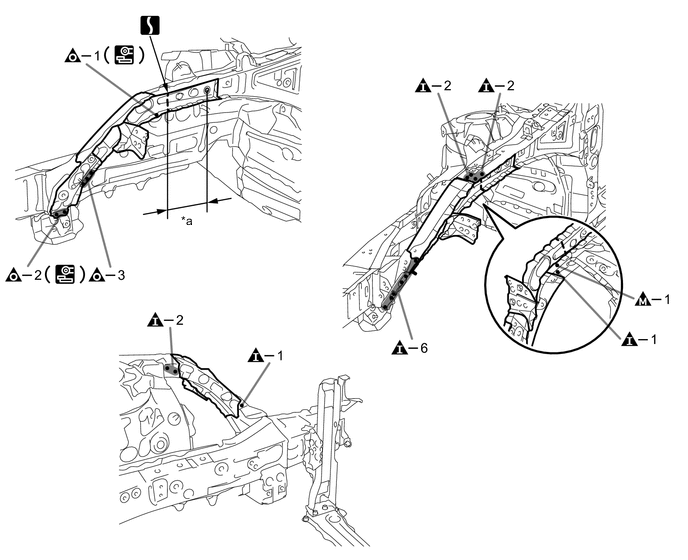
*a 130 mm (5.12 in.) - - -
INSTALLATION
Symbol Meaning 
Plug Weld 
Plug Weld 
Plug Weld 
Butt Weld
-
Inspect the fitting of the related parts around the new parts before welding. This affects the appearance of the finish.
-
Temporarily install the new parts and measure each part of the new parts in accordance with the body dimension diagram. (See the body dimensions)
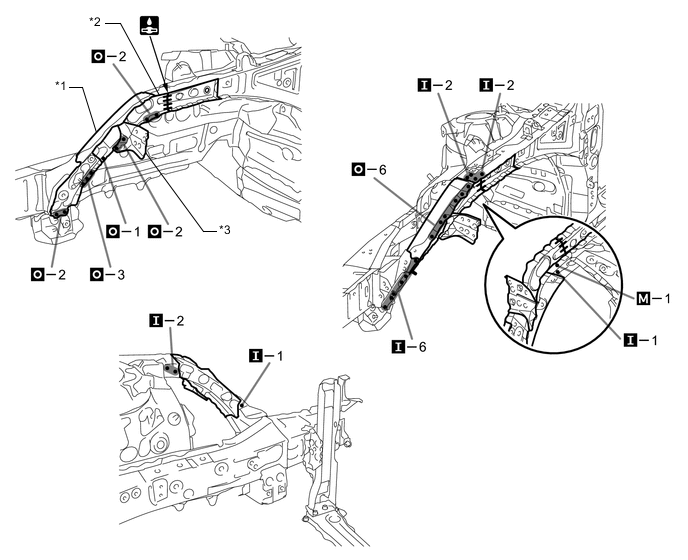
*1 FENDER SIDE APRON SUB-ASSEMBLY *2 FRONT APRON TO COWL SIDE MEMBER LOWER FRONT *3 FRONT FENDER APRON GUSSET UPPER - - -
After welding, apply body sealer to the corresponding parts. (See the painting/coating)
-
After applying the top coat, apply anti-rust agent to the internal panel portion of the closed section structural weld points.
-