LIGHTING SYSTEM
-
FUNCTION OF MAIN COMPONENTS
-
Daytime Running Light System
Component Function Main Body ECU (Network Gateway ECU) The main body ECU (network gateway ECU) receives various signals and illuminates the daytime running lights via the DRL relay. Headlight Dimmer Switch Assembly Light Control Switch The light control switch outputs a light control signal and transmits it to the main body ECU (network gateway ECU). Ignition Switch (Ignition or Starter Switch Assembly)*1 The ignition switch outputs the ignition switch status and transmits it to the main body ECU (network gateway ECU). Parking Brake Switch Assembly The parking brake switch assembly outputs the parking brake status (on/off) and transmits it to the main body ECU (network gateway ECU). ECM
-
The ECM outputs an engine speed signal and transmits it to the main body ECU (network gateway ECU).
-
The ECM outputs the shift position signal and transmits it to the main body ECU (network gateway ECU). *2
Transmission Control ECU Assembly*3 The transmission control ECU assembly outputs the shift position signal and transmits it to the main body ECU (network gateway ECU).
-
*1: Models without entry and start system
-
*2: Models with M/T
-
*3: Models with A/T
-
-
HID Headlight System
Component Function Main Body ECU (Network Gateway ECU) The main body ECU (network gateway ECU) receives the HEAD position signal and transmit a signal to the headlight light control ECU sub-assembly. Headlight Dimmer Switch Assembly Light Control Switch The light control switch outputs a HEAD position signal and transmits it to the main body ECU (network gateway ECU). Headlight Assembly Shade Shade receives a signal from the main body ECU (network gateway ECU) and switches between low beams and high beams according to the revolutions. Headlight Light Control ECU Sub-assembly The headlight light control ECU sub-assembly transforms battery voltage to a high voltage of up to 22000 V and applies it to the discharge headlight bulbs in order to illuminate them. Discharge Headlight Bulb The discharge headlight bulb light shines ahead over a broader area and further forward, increasing the area visible to the driver. -
Automatic Headlight Beam Level Control System
Component Function Headlight Leveling ECU Assembly
-
The headlight leveling ECU assembly detects changes of vehicle movement based on the rear height control sensor sub-assembly LH and vehicle speed signal.
-
The headlight leveling ECU assembly outputs control signals to the headlight leveling motors based on the detected value.
-
This ECU provides initial set control and a fail-safe function.
Rear Height Control Sensor Sub-assembly LH The rear height control sensor sub-assembly LH detects vehicle movement and transmits a signal to the headlight leveling ECU assembly. Skid Control ECU The skid control ECU transmits a vehicle speed signal to the headlight leveling ECU assembly. Combination Meter Assembly Automatic Headlight Beam Level Indicator Light The automatic headlight beam level indicator light flashes to inform the driver when the headlight leveling ECU assembly detects malfunctions in this system. Headlight Assembly Headlight Leveling Motor
-
Based on the signals received from headlight leveling ECU assembly, each headlight leveling motor moves the projector unit in the headlight to vary its angle.
-
Each headlight leveling motor uses a stepper motor to precisely regulate the angle of the projector unit.
-
-
Manual Headlight Beam Level Control System
Component Function Headlight Leveling Switch Sends control signals to the headlight leveling motor. Headlight Assembly Headlight Leveling Motor
-
Based on the signals received from headlight leveling switch, each motor moves the reflector in the headlight to vary its low beam angle.
-
Each headlight leveling motor uses a stepper motor to precisely regulate the angle of the reflector.
-
-
Automatic Light Control System
Component Function Main Body ECU (Network Gateway ECU) The main body ECU (network gateway ECU) receives various signals and illuminates the headlights, taillights, clearance lights, side marker lights*1 and license plate lights. Headlight Dimmer Switch Assembly Light Control Switch The light control switch transmits an AUTO position signal to the main body ECU (network gateway ECU). Ignition Switch (Ignition or Starter Switch Assembly)*2 The ignition switch outputs the ignition switch status and transmits it to the main body ECU (network gateway ECU). Automatic Light Control Sensor The automatic light control sensor detects the ambient light level.
-
*1: Models for Korea
-
*2: Models without entry and start system
-
-
Light Auto Turn-off System
Component Function Main Body ECU (Network Gateway ECU) The main body ECU (network gateway ECU) receives various signals, and turns off the exterior lights. Headlight Dimmer Switch Assembly Light Control Switch The light control switch transmits a light control position signal to the main body ECU (network gateway ECU). Ignition Switch (Ignition or Starter Switch Assembly)* The ignition switch outputs the ignition switch status and transmits it to the main body ECU (network gateway ECU).
-
*: Models without entry and start system
-
-
-
OPERATING CONDITION
-
Daytime Running Light System
-
The daytime running lights illuminate when the following conditions are met:
-
Ignition switch is ON.
-
Engine is running.
-
The low beams are not on.
-
The parking brake is off.
-
-
-
Follow Me Home System
-
The follow me home system is enabled when the following conditions are met:
-
Ignition switch and ACC is OFF.
-
Light control switch OFF or AUTO position.
-
The headlight dimmer switch assembly is pulled to flash headlights once.
-
The key is removed from the ignition key cylinder.*
-
*: Models without entry and start system
-
-
-
Light Auto Turn-off System
-
The exterior lights automatically turn off when all of the following conditions are met:
-
The ignition switch is turned (or ACC) from on to off.
-
The key is removed from the ignition key cylinder.*
-
*: Models without entry and start system
-
-
-
Light Remminder System
-
The light reminder system will sound a buzzer if the following conditions are met:
-
The headlight dimmer switch assembly is in the head or tail position.
-
Ignition switch is OFF.
-
The key is removed from the ignition key cylinder.*
-
The driver door is opened.
-
*: Models without entry and start system
-
-
-
-
FUNCTION
-
HID Headlight System
-
The HID headlight system consists of discharge headlight bulbs and headlight light control ECU sub-assembly.
-
Headlight light control ECU sub-assembly transforms the voltage that is input from the battery to a high voltage of up to 22000 V and applies it to the discharge headlight bulbs in order to illuminate them.
-
A fail-safe function is provided as a countermeasure against the high voltage generated when a problem occurs in the headlight system.
-
-
Automatic Headlight Beam Level Control System
-
The automatic headlight beam level control system mainly consists of the headlight leveling ECU assembly, rear height control sensor sub-assembly LH and 2 headlight leveling motors. The headlight leveling ECU assembly controls the system.
-
The ECU detects the movement of the suspension from the rear height control sensor sub-assembly LH and the vehicle speed from the skid control ECU.
-
The ECU then controls the headlight leveling motor based on this information, in order to change the headlight reflector angle.
-
When the engine is started, the headlight leveling ECU assembly drives the headlight leveling motor, moves the headlight reflector to the lower limit position and returns it to the proper position. The headlight leveling ECU assembly thus assesses the position of the headlight for reference control.
-
-
Follow Me Home System
-
The follow me home system is controlled by the main body ECU (network gateway ECU). The main body ECU (network gateway ECU) illuminates the low beam.
-
-
Light Reminder System
-
The light reminder system warns the driver using a buzzer when the main body ECU (network gateway ECU) detects a change in the driver's door courtesy light switch and sends a buzzer sound request signal to the combination meter assembly, if the ignition switch is turned off and the door is opened with the taillights kept on. The buzzer is located inside the combination meter assembly.
Light control switch position Ignition Switch (Ignition or Starter Switch Assembly) Door Buzzer Tail, Head switch off Open Sounds Closed -
-
-
-
CONSTRUCTION
-
HID Headlight System
-
Discharge Headlight Bulb
Instead of the filament contained in an incandescent bulb, a discharge headlight bulb contains an arc tube, which is filled with xenon gas, and metal halide.
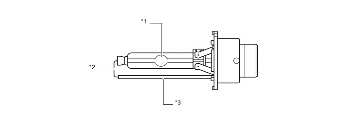
Text in Illustration *1 Arc Tube *2 Lead Wire *3 Ceramic Pipe - - -
Discharge headlight bulbs have the following advantages:
-
The light emitted by the bulb is close in color to sunlight. The light shines ahead over a broader area and further forward, increasing the area visible to the driver.
-
Less power is consumed.
-
-
-
-
FAIL-SAFE
-
HID Headlight System
-
The headlight light control ECU sub-assembly executes the fail-safe actions listed below in accordance with the problem that has been detected:
Problem Outline Detection of Abnormal Input Voltage If the voltage input to the headlight light control ECU sub-assembly deviates from the normal operating voltage (10 V to 16 V), the headlight light control ECU sub-assembly stops illuminating the headlights. It resumes illuminating the headlights once the voltage reverts to the normal operating voltage range. However, if the input voltage decreases after the headlights have illuminated, the headlights will remain illuminated until the input voltage is insufficient to light the bulbs. Detection of Abnormal Output (Open Circuit or Short Circuit) If an abnormal condition (open or short) occurs in the voltage that is output by headlight light control ECU sub-assembly, the headlight light control ECU sub-assembly stops illuminating the headlights and will maintain this state until the power is reinstated. Power is reinstated by turning the light control switch from off to on. Detection of Abnormal Light Voltage If voltage abnormality of the headlight is detected by headlight light control ECU sub-assembly, the headlight light control ECU sub-assembly stops illuminating the headlights and will maintain this state until the power is reinstated. Power is reinstated by turning the light control switch from off to on.
-
-
Automatic Headlight Beam Level Control System
-
If the headlight leveling ECU assembly detects a malfunction in the automatic headlight beam level control system, it will take the actions indicated in the table below:
Trouble Item System Operation Automatic Headlight Level Indicator Light Ignition Power Over-Voltage Output of control signal to headlight leveling motor stops. Extinguished Ignition Power Under-Voltage Extinguished Rear Height Control Sensor Sub-assembly LH Power Over-Voltage Flashes Rear Height Control Sensor Sub-assembly LH Power Under-Voltage Flashes Rear Height Control Sensor Sub-assembly LH Signal Error Flashes Rear Height Control Sensor Sub-assembly LH Data Error During Initialization Flashes
-
-
-
DIAGNOSIS
-
Automatic Light Control System
-
When the main body ECU (network gateway ECU) detects malfunctions in the automatic light control system, Diagnostic Trouble Codes (DTCs) are stored in memory.
-
The DTCs can be read using the Grobal TechStream (GTS). For details, refer to the Repair Manual.
-
-