ENGINE UNIT INSPECTION
PROCEDURE
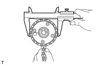
INSPECT CHAIN SUB-ASSEMBLY
-
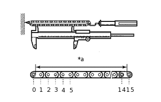
*a
Measurement Length
Pull the chain sub-assembly with a force of 147 N (15 kgf, 33.0 lbf) as shown in the illustration.
Using a vernier caliper, measure the length of 15 links.
Maximum chain elongation
115.2 mm (4.54 in.)
Note:Perform the measurement at 3 random places. Use the average of the measurements.
If the average elongation is more than the maximum, replace the chain sub-assembly.
-
INSPECT NO. 2 CHAIN SUB-ASSEMBLY
-

*a
Measurement Length
Pull the No. 2 chain sub-assembly with a force of 147 N (15 kgf, 33.0 lbf) as shown in the illustration.
Using a vernier caliper, measure the length of 15 links.
Maximum chain elongation
102.1 mm (4.02 in.)
Note:Perform the measurement at 3 random places. Use the average of the measurements.
If the average elongation is more than the maximum, replace the No. 2 chain sub-assembly.
-
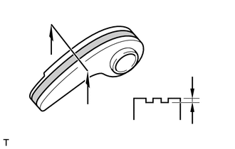
INSPECT OIL PUMP DRIVE GEAR
-
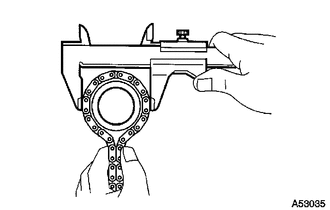
Place the No. 2 chain sub-assembly around the oil pump drive gear.
Using a vernier caliper, measure the diameter of the oil pump drive gear and No. 2 chain sub-assembly.
Minimum gear diameter (with chain)
48.2 mm (1.90 in.)
Note:The vernier caliper must be in contact with the chain rollers when measuring.
If the diameter is less than the minimum, replace the No. 2 chain sub-assembly and oil pump drive gear.
-
INSPECT OIL PUMP DRIVE SHAFT GEAR
-
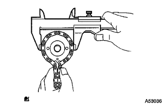
Place the No. 2 chain sub-assembly around the oil pump drive shaft gear.
Using a vernier caliper, measure the diameter of the oil pump drive shaft gear and No. 2 chain sub-assembly .
Minimum gear diameter (with chain)
48.2 mm (1.90 in.)
Note:The vernier caliper must be in contact with the No. 2 chain sub-assembly rollers when measuring.
If the diameter is less than the minimum, replace the No. 2 chain sub-assembly and oil pump drive shaft gear.
-
INSPECT CAMSHAFT TIMING GEAR ASSEMBLY
-
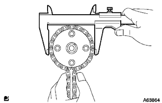
Place the chain sub-assembly around the camshaft timing gear assembly.
Using a vernier caliper, measure the diameter of the camshaft timing gear assembly and chain sub-assembly.
Minimum gear diameter (with chain)
96.8 mm (3.81 in.)
Note:The vernier caliper must be in contact with the chain sub-assembly rollers when measuring.
If the diameter is less than the minimum, replace the chain sub-assembly and camshaft timing gear assembly.
-
INSPECT CAMSHAFT TIMING EXHAUST GEAR ASSEMBLY
-
Place the chain sub-assembly around the camshaft timing exhaust gear assembly.
Using a vernier caliper, measure the diameter of the camshaft timing exhaust gear assembly and chain sub-assembly.
Minimum gear diameter (with chain)
96.8 mm (3.81 in.)
Note:The vernier caliper must be in contact with the chain sub-assembly rollers when measuring.
If the diameter is less than the minimum, replace the chain sub-assembly and camshaft timing exhaust gear assembly.
-
INSPECT CRANKSHAFT TIMING GEAR
-
Place the chain sub-assembly around the crankshaft timing gear.
Using a vernier caliper, measure the diameter of the crankshaft timing gear and chain sub-assembly.
Minimum gear diameter (with chain)
51.1 mm (2.01 in.)
Note:The vernier caliper must be in contact with the chain sub-assembly rollers when measuring.
If the diameter is less than the minimum, replace the chain sub-assembly and crankshaft timing gear.
-
INSPECT CHAIN TENSIONER SLIPPER
-
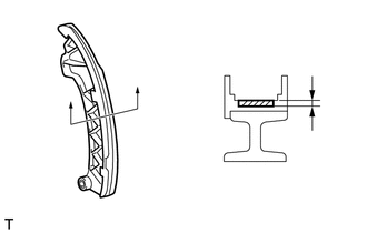
Using a vernier caliper, measure the chain tensioner slipper wear.
Maximum wear
1.0 mm (0.0394 in.)
If the wear is more than the maximum, replace the chain tensioner slipper.
-
INSPECT NO. 1 CHAIN VIBRATION DAMPER
-
Using a vernier caliper, measure the No. 1 chain vibration damper wear.
Maximum wear
1.0 mm (0.0394 in.)
If the wear is more than the maximum, replace the No. 1 chain vibration damper.
-
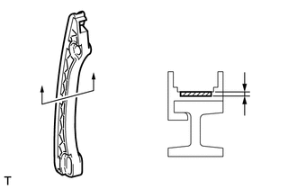
INSPECT CHAIN TENSIONER PLATE
-
Using a vernier caliper, measure the chain tensioner plate wear.
Maximum wear
1.0 mm (0.0394 in.)
If the wear is more than the maximum, replace the chain tensioner plate.
-
INSPECT NO. 1 CHAIN TENSIONER ASSEMBLY
-
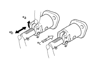
*a
Raise
*b
Move
*c
Lock
Check that the plunger moves smoothly when the cam is raised with your finger.
Release the cam, then check that the plunger is locked in place by the cam and does not move when pushed with your finger.
If necessary, replace the No. 1 chain tensioner assembly.
-
INSPECT CYLINDER HEAD SET BOLT
-
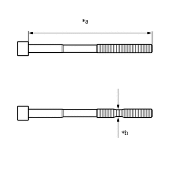
*a
Measurement length
*b
Measurement point
Using a vernier caliper, measure the length of the bolt from the seat to the end.
Standard length
146.8 to 148.2 mm (5.78 to 5.83 in.)
Maximum length
149.2 mm (5.87 in.)
Tip:If the length is greater than the maximum, replace the cylinder head set bolt with a new one. Failure to do so may lead to engine damage.
If there is any thread deformation, replace the cylinder head set bolt with a new one.
Using a vernier caliper, measure the diameter of the threaded portion of the bolt at its thinnest point shown in the illustration.
Tip:Use a straightedge to determine the thinnest point of the threaded portion of the bolt.
Measurement point
115 mm (4.53 in.)
Standard diameter
9.77 to 9.96 mm (0.385 to 0.392 in.)
Minimum diameter
9.4 mm (0.370 in.)
Tip:If the diameter is less than the minimum, replace the cylinder head set bolt with a new one. Failure to do so may lead to engine damage.
If there is any thread deformation, replace the cylinder head set bolt with a new one.
-
INSPECT EXHAUST MANIFOLD
-
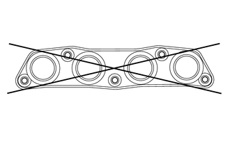
Using a precision straightedge and feeler gauge, measure the warpage on the surface that contacts the cylinder head sub-assembly.
Maximum warpage
0.7 mm (0.0276 in.)
If the warpage is more than the maximum, replace the exhaust manifold.
-