SFI SYSTEM(w/ EGR System), Diagnostic DTC:P0107 and P0108
| DTC Code | DTC Name |
|---|---|
| P0107 | Manifold Absolute Pressure / Barometric Pressure Circuit Low Input |
| P0108 | Manifold Absolute Pressure / Barometric Pressure Circuit High Input |
DESCRIPTION
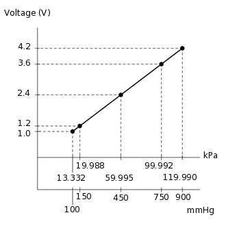
The manifold absolute pressure sensor detects the intake manifold pressure as a voltage using a built-in sensor unit.
DTC No. |
Detection Item |
DTC Detection Condition |
Trouble Area |
Warning Indicate |
Memory |
|---|---|---|---|---|---|
P0107 |
Manifold Absolute Pressure / Barometric Pressure Circuit Low Input |
The manifold absolute pressure sensor voltage is below 0.5 V for 0.5 seconds (1 trip detection logic). |
|
Comes on |
DTC stored |
P0108 |
Manifold Absolute Pressure / Barometric Pressure Circuit High Input |
The manifold absolute pressure sensor voltage is higher than 4.5 V for 0.5 seconds (1 trip detection logic). |
|
Comes on |
DTC stored |
When either of these DTCs is output, check the manifold absolute pressure using the intelligent tester. Enter the following menus: Powertrain / Engine and ECT / Data List / All Data / MAP.
MAP |
Malfunction |
|---|---|
Approximately 0 kPa |
|
130 kPa or higher |
|
MONITOR DESCRIPTION
The ECM monitors the sensor voltage and uses this value to calculate the manifold absolute pressure. When the sensor output voltage deviates from the normal operating range, the ECM interprets this as a malfunction in the manifold pressure sensor and stores a DTC.
Example:
When the sensor output voltage remains below 0.5 V, or higher than 4.5 V for more than 0.5 seconds, the ECM stores a DTC.
If the malfunction is not repaired successfully, a DTC is stored 0.5 seconds after the engine is next started.
MONITOR STRATEGY
Frequency of Operation |
Continuous |
CONFIRMATION DRIVING PATTERN
Turn the engine switch on (IG) and wait for 5 seconds or more.
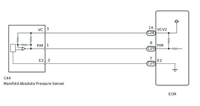
WIRING DIAGRAM
CAUTION / NOTICE / HINT
If other DTCs related to different systems that have terminal E2 as the ground terminal are stored simultaneously, there may be an open circuit between terminal E2 and body ground.
Read freeze frame data using the intelligent tester. The ECM records vehicle and driving condition information as freeze frame data the moment a DTC is stored. When troubleshooting, freeze frame data can help determine if the vehicle was moving or stationary, if the engine was warmed up or not, if the air fuel ratio was lean or rich, and other data from the time the malfunction occurred.
PROCEDURE
READ VALUE USING INTELLIGENT TESTER (MAP)
Connect the intelligent tester to the DLC3.
Start the engine.
Turn the tester on.
Enter the following menus: Powertrain / Engine and ECT / Data List / MAP.
Powertrain > Engine and ECT > Data List
Tester Display
MAP
Read the MAP value.
OK
Same value as the actual atmospheric pressure.
Tip:Standard atmospheric pressure is 101 kPa. For every 100 m increase in elevation, pressure drops by 1 kPa. This varies by weather (high atmospheric pressure, low atmospheric pressure).
Also, check "Atmosphere Pressure" in the Data List.
Result
Result
OK
NG
CHECK MANIFOLD ABSOLUTE PRESSURE SENSOR (TERMINAL VOLTAGE)
-
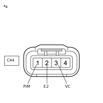
*1
Front view of wire harness connector
(to Manifold Absolute Pressure Sensor)
Disconnect the manifold absolute pressure sensor connector.
Turn the engine switch on (IG).
Measure the voltage according to the value(s) in the table below.
Standard Voltage
Tester Connection
Switch Condition
Specified Condition
C44-3 (VC) - C44-2 (E2)
Engine switch on (IG)
4.5 to 5.5 V
C44-1 (PIM) - C44-2 (E2)
Engine switch on (IG)
4.0 to 5.0 V
Result
Result
OK
NG
NG CHECK HARNESS AND CONNECTOR (MANIFOLD ABSOLUTE PRESSURE SENSOR - ECM)Click here
-
REPLACE MANIFOLD ABSOLUTE PRESSURE SENSOR
Replace the manifold absolute pressure sensor.
Result
Result
NEXT
CHECK WHETHER DTC OUTPUT RECURS
Connect the intelligent tester to the DLC3.
Turn the engine switch on (IG) and turn the tester on.
Clear the DTCs.
Powertrain > Engine and ECT > Clear DTCs
Turn the engine switch off and wait for at least 30 seconds.
Turn the engine switch on (IG) and wait for 5 seconds.
Turn the tester on.
Enter the following menus: Powertrain / Engine and ECT / DTC.
Read the DTCs.
Powertrain > Engine and ECT > Trouble Codes
Result
Result
Proceed to
Display (DTC output)
A
DTC P0107 and/or P0108 output
B
A END
CHECK HARNESS AND CONNECTOR (MANIFOLD ABSOLUTE PRESSURE SENSOR - ECM)
Disconnect the manifold absolute pressure sensor connector.
Disconnect the ECM connector.
Measure the resistance according to the value(s) in the table below.
Standard Resistance (Check for open)
Tester Connection
Condition
Specified Condition
C44-1 (PIM) - C29-8 (PIM)
Always
Below 1 Ω
C44-3 (VC) - C28-16 (VCV2)
Always
Below 1 Ω
C44-2 (E2) - C29-7 (E2)
Always
Below 1 Ω
Standard Resistance (Check for short)
Tester Connection
Condition
Specified Condition
C44-1 (PIM) or C29-8 (PIM) - Body ground
Always
10 kΩ or higher
C44-3 (VC) or C28-16 (VCV2) - Body ground
Always
10 kΩ or higher
Result
Result
OK
NG
NG REPAIR OR REPLACE HARNESS OR CONNECTOR