SFI SYSTEM, Diagnostic DTC:P244B00
| DTC Code | DTC Name |
|---|---|
| P244B00 | Particulate Filter Differential Pressure Too High Bank 1 |
DESCRIPTION
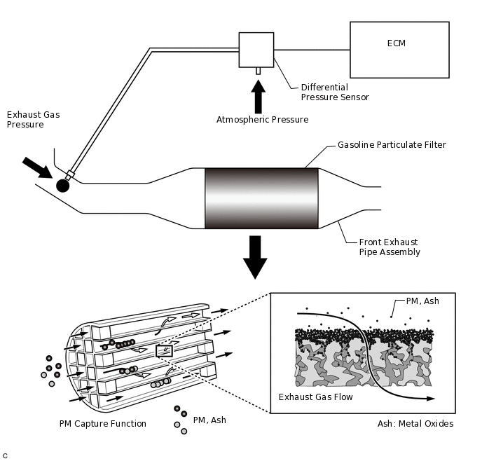
The GPF (Gasoline Particulate Filter) system is an exhaust purification system for processing the PM (Particulate Matter) discharged from the engine. The GPF catalyst has a porous ceramic structure that collects PM, and the collected PM is oxidized as it bonds with oxygen molecules under high temperature. When the fuel cut operation is performed after the GPF rises to a high temperature under high load operation, PM is oxidized, but under low temperature conditions, PM oxidation is insufficient and deposits accumulate. When the GPF is clogged by PM and "Exhaust Filter Regeneration In Process" or "Exhaust Filter Full" is displayed on the multi-information display or GPF warning light is comes on, perform particulate filter rejuvenation using the GTS.
A differential pressure sensor is installed to monitor the pressure before the GPF catalyst converter. The sensor is a semiconductor type that is not affected by the exhaust gas. The differential pressure sensor outputs the difference between the atmospheric pressure and the pressure before the GPF catalyst. The differential pressure sensor outputs the difference between the atmospheric pressure and the pressure before the GPF catalyst.
DTC No. |
Detection Item |
DTC Detection Condition |
Trouble Area |
MIL |
Memory |
Note |
|---|---|---|---|---|---|---|
P244B00 |
Particulate Filter Differential Pressure Too High Bank 1 |
Differential pressure sensor (bank 1) output value at intake air flow of 30 gm/sec*1 or higher is at the threshold*2 or higher (1 trip detection logic). |
|
Comes on |
DTC stored |
SAE Code: P244B |
*1: The total value of Mass Air Flow Sensor
*2: Threshold differs according to intake air flow
MONITOR DESCRIPTION
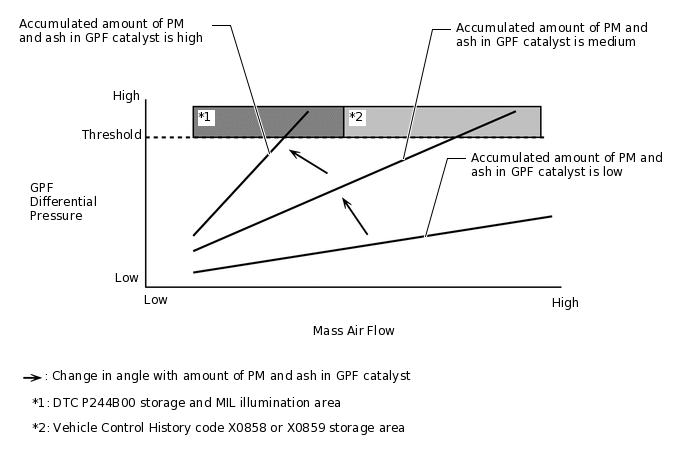
The differential pressure sensor outputs the difference between the atmospheric pressure and the pressure before the GPF catalyst. When the GPF differential pressure is at the threshold or higher due to PM or ash accumulation in the GPF catalyst, output is limited during high load operation. At this time, the ECM illuminates the MIL and stores a DTC.
MONITOR STRATEGY
Frequency of Operation |
Once per driving cycle |
CONFIRMATION DRIVING PATTERN
Connect the GTS to the DLC3.
Turn the ignition switch to ON.
Turn the GTS on.
Clear the DTCs (even if no DTCs are stored, perform the clear DTC procedure).
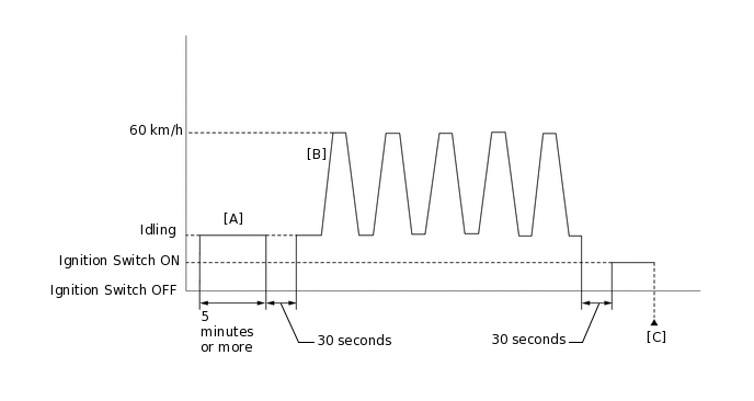
Idle the engine for 5 minutes or more [A].
Turn the ignition switch off and wait for at least 30 seconds.
Start the engine.
Repeat the pattern of accelerating the vehicle from rest to approximately 60 km/h (37 mph) [depress the accelerator pedal by a large amount at 2nd shift position] and then decelerating the vehicle 5 times [B].
CAUTION:When performing the confirmation driving pattern, obey all speed limits and traffic laws.
Turn the ignition switch off and wait for at least 30 seconds.
Turn the ignition switch to ON.
Turn the GTS on.
Enter the following menus: Powertrain / Engine / Trouble Codes [C].
Read the pending DTCs.
Tip:If a pending DTC is output, the system is malfunctioning.
If a pending DTC is not output, perform the following procedure.
Enter the following menus: Powertrain / Engine / Utility / All Readiness.
Input the DTC: P244B00.
Check the DTC judgment result.
GTS Display
Description
NORMAL
DTC judgment completed
System normal
ABNORMAL
DTC judgment completed
System abnormal
INCOMPLETE
DTC judgment not completed
Perform driving pattern after confirming DTC enabling conditions
Tip:If the judgment result is NORMAL, the system is normal.
If the judgment result is ABNORMAL, the system has a malfunction.
If the judgment result is INCOMPLETE, perform steps [A] through [C] again.
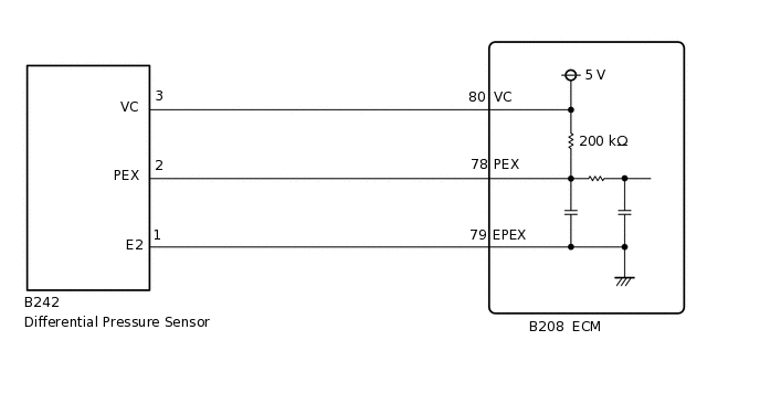
WIRING DIAGRAM
Refer to DTC P010012 for the mass air flow meter sub-assembly circuit.
Differential pressure sensor circuit
CAUTION / NOTICE / HINT
Clear the Vehicle Control History after completing repairs.
Read Freeze Frame Data using the GTS. The ECM records vehicle and driving condition information as Freeze Frame Data the moment a DTC is stored. When troubleshooting, Freeze Frame Data can help determine if the vehicle was moving or stationary, if the engine was warmed up or not, if the air fuel ratio was lean or rich, and other data from the time the malfunction occurred.
PROCEDURE
CHECK ANY OTHER DTCS OUTPUT (IN ADDITION TO DTC P244B00)
Connect the GTS to the DLC3.
Turn the ignition switch to ON.
Turn the GTS on.
Enter the following menus: Powertrain / Engine / Utility / Vehicle Control History (RoB).
Powertrain > Engine > Utility
Tester Display
Vehicle Control History (RoB)
Record the Vehicle Control History.
Enter the following menus: Powertrain / Engine / Trouble Codes.
Read the DTCs.
Powertrain > Engine > Trouble Codes
Result
Result
Proceed to
DTC P244B00 is output
A
DTC P244B00 and other DTCs are output
B
Tip:If any DTCs other than P244B00 are output, troubleshoot those DTCs first.
READ VALUE USING GTS (ASH DEPOSITION RATIO)
Connect the GTS to the DLC3.
Turn the ignition switch to ON.
Turn the GTS on.
Enter the following menus: Powertrain / Engine / Data List / Ash Deposition Ratio Bank1.
Powertrain > Engine > Data List
Tester Display
Ash Deposition Ratio Bank1
Read the value displayed on the GTS.
Standard
GTS Display
Specified Condition
Ash Deposition Ratio Bank1
Less than 100%
Result
Proceed to
OK
NG
Tip:Clear the GPF deterioration record using the GTS after replacing the front exhaust pipe assembly (GPF).
CLEAR DTC
Connect the GTS to the DLC3.
Turn the ignition switch to ON.
Turn the GTS on.
Clear the DTCs.
Powertrain > Engine > Clear DTCs
Turn the ignition switch off and wait for at least 30 seconds.
Result
Proceed to
NEXT
READ VALUE USING GTS (PM DEPOSITION RATIO)
Turn the ignition switch to ON.
Turn the GTS on.
Enter the following menus: Powertrain / Engine / Data List / PM Deposition Ratio Bank 1.
Powertrain > Engine > Data List
Tester Display
PM Deposition Ratio Bank1
Read the values displayed on the GTS.
Tip:Data List item "PM Deposition Ratio Bank1" is necessary after performing particulate filter rejuvenate. Therefore, make sure check them.
Result
Proceed to
NEXT
PERFORM PM REJUVENATE MODE
Perform the PM Rejuvenate Mode.
Result
Proceed to
NEXT
READ VALUE USING GTS (PM DEPOSITION RATIO)
Connect the GTS to the DLC3.
Turn the ignition switch to ON.
Turn the GTS on.
Enter the following menus: Powertrain / Engine / Data List / PM Deposition Ratio Bank 1.
Powertrain > Engine > Data List
Tester Display
PM Deposition Ratio Bank1
Read the values displayed on the GTS.
Standard
GTS Display
Specified Condition
PM Deposition Ratio Bank1
Less than 30%
Tip:After performing particulate filter rejuvenate, if the value of Data List items "PM Deposition Ratio Bank1" is less than the value during step 4 (READ VALUE USING GTS (PM DEPOSITION RATIO)), the driving condition may not be suitable for particulate filter rejuvenate. Therefore, perform particulate filter rejuvenate again.
Result
Proceed to
OK
NG
NG INSPECT DIFFERENTIAL PRESSURE SENSORClick here
CLEAR DTC
Connect the GTS to the DLC3.
Turn the ignition switch to ON.
Turn the GTS on.
Clear the DTCs.
Powertrain > Engine > Clear DTCs
Turn the ignition switch off and wait for at least 30 seconds.
Result
Proceed to
NEXT
CHECK WHETHER DTC OUTPUT RECURS (DTC P244B00)
Drive the vehicle in accordance with the driving pattern described in the Confirmation Driving Pattern.
Enter the following menus: Powertrain / Engine / Trouble Codes.
Read the DTCs.
Powertrain > Engine > Trouble Codes
Result
Result
Proceed to
DTCs are not output
A
DTC P244B00 is output
B
A END
B INSPECT DIFFERENTIAL PRESSURE SENSORClick here
INSPECT DIFFERENTIAL PRESSURE SENSOR
Inspect the differential pressure sensor.
Result
Proceed to
OK
NG
NG CHECK HARNESS AND CONNECTOR (DIFFERENTIAL PRESSURE SENSOR - ECM)Click here
READ VALUE USING GTS (MASS AIR FLOW SENSOR)
Connect the GTS to the DLC3.
Turn the ignition switch to ON.
Turn the GTS on.
Enter the following menus: Powertrain / Engine / Data List / Engine Speed, Mass Air Flow Sensor and Coolant Temperature.
Powertrain > Engine > Data List
Tester Display
Engine Speed
Mass Air Flow Sensor
Coolant Temperature
Allow the engine to idle until Coolant Temperature reaches 75°C (167°F) or higher.
Read Mass Air Flow Sensor while maintaining an engine speed of 3000 rpm.
Standard
GTS Display
Condition
Specified Condition
Mass Air Flow Sensor
Shift lever position: P or neutral
A/C: Off
Engine warmed up
Engine Speed: 3000 rpm
Between 4.0 and 14.0 gm/sec
Result
Proceed to
OK
NG
Tip:Clear the GPF deterioration record using the GTS after replacing the front exhaust pipe assembly (GPF).
CHECK TERMINAL VOLTAGE (POWER SOURCE OF MASS AIR FLOW METER SUB-ASSEMBLY)
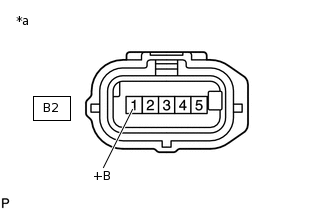
*a
Front view of wire harness connector
(to Mass Air Flow Meter Sub-assembly)
Disconnect the mass air flow meter sub-assembly connector.
Turn the ignition switch to ON.
Measure the voltage according to the value(s) in the table below.
Standard Voltage
Tester Connection
Condition
Specified Condition
B2-1 (+B) - Body ground
Ignition switch ON
11 to 14 V
Result
Proceed to
OK
NG
NG REPAIR OR REPLACE HARNESS OR CONNECTOR (EFI-MAIN RELAY - MASS AIR FLOW METER SUB-ASSEMBLY)
CHECK HARNESS AND CONNECTOR (MASS AIR FLOW METER SUB-ASSEMBLY - ECM)
Disconnect the mass air flow meter sub-assembly connector.
Disconnect the ECM connector.
Measure the resistance according to the value(s) in the table below.
Standard Resistance
Tester Connection
Condition
Specified Condition
B2-3 (VG) - B208-92 (VG)
Always
Below 1 Ω
B2-2 (E2G) - B208-91 (E2G)
Always
Below 1 Ω
B2-3 (VG) or B208-92 (VG) - Body ground and other terminals
Always
10 kΩ or higher
Result
Proceed to
OK
NG
NG REPAIR OR REPLACE HARNESS OR CONNECTOR
CHECK HARNESS AND CONNECTOR (SENSOR GROUND)
Disconnect the mass air flow meter sub-assembly connector.
Measure the resistance according to the value(s) in the table below.
Standard Resistance
Tester Connection
Condition
Specified Condition
B2-2 (E2G) - Body ground
Always
Below 1 Ω
Result
Proceed to
OK
NG
INSPECT MASS AIR FLOW METER SUB-ASSEMBLY
Inspect the mass air flow meter sub-assembly, referring to On-vehicle Inspection for Mass Air Flow Meter.
Inspect the mass air flow meter sub-assembly, referring to Inspection for Mass Air Flow Meter.
Inspect the function of the mass air flow meter sub-assembly.
Connect the GTS to the DLC3.
Turn the ignition switch to ON.
Turn the GTS on.
Enter the following menus: Powertrain / Engine / Data List / Mass Air Flow Sensor.
Powertrain > Engine > Data List
Tester Display
Mass Air Flow Sensor
Start the engine.
Check that the Mass Air Flow Sensor value changes when the engine is raced.
OK
The reading changes.
Tip:Perform "Inspection After Repair" after replacing the mass air flow meter sub-assembly.
Result
Proceed to
OK
NG
CHECK HARNESS AND CONNECTOR (DIFFERENTIAL PRESSURE SENSOR - ECM)
Disconnect the differential pressure sensor connector.
Disconnect the ECM connector.
Measure the resistance according to the value(s) in the table below.
Standard Resistance
Tester Connection
Condition
Specified Condition
B242-3 (VC) - B208-80 (VC)
Always
Below 1 Ω
B242-2 (PEX) - B208-78 (PEX)
Always
Below 1 Ω
B242-1 (E2) - B208-79 (EPEX)
Always
Below 1 Ω
B242-3 (VC) or B208-80 (VC) - Body ground and other terminals
Always
10 kΩ or higher
B242-2 (PEX) or B208-78 (PEX) - Body ground and other terminals
Always
10 kΩ or higher
Result
Proceed to
OK
NG
NG REPAIR OR REPLACE HARNESS OR CONNECTOR
REPLACE DIFFERENTIAL PRESSURE SENSOR
Replace the differential pressure sensor.
Start the engine and allow it to idle until the engine coolant temperature reaches 75°C (167°F) or higher (A).
Turn the ignition switch off and wait for 30 seconds or more (B).
Repeat the above procedures (A) and (B) 3 times.
Tip:Procedures (A) and (B) must be repeated 3 times to complete the differential pressure sensor learning process.
Result
Proceed to
NEXT
NEXT END