BRAKE PEDAL INSTALLATION
PROCEDURE
INSTALL BRAKE PEDAL SUPPORT SUB-ASSEMBLY
-
Install the nut to the brake pedal support sub-assembly.
-
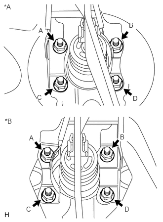
Install the brake pedal support sub-assembly with the 4 nuts. Tighten the 4 nuts uniformly in alphabetical order.
13 N*m
130 kgf*cm
9 ft.*lbf
Table 1. Text in Illustration *A
for LHD
*B
for RHD
-
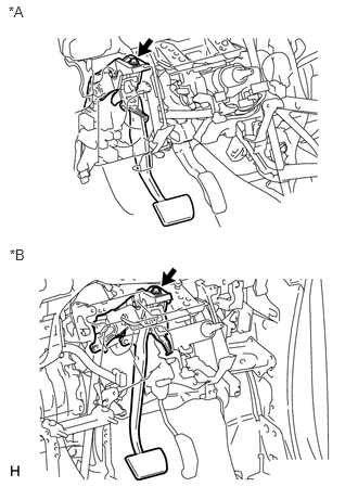
Install the brake pedal support sub-assembly to the instrument panel reinforcement with the bolt.
24 N*m
241 kgf*cm
17 ft.*lbf
Table 2. Text in Illustration *A
for LHD
*B
for RHD
-
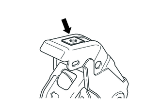
INSTALL STOP LIGHT SWITCH ASSEMBLY
Install the stop light switch assembly (Click here).
INSTALL PUSH ROD PIN
-
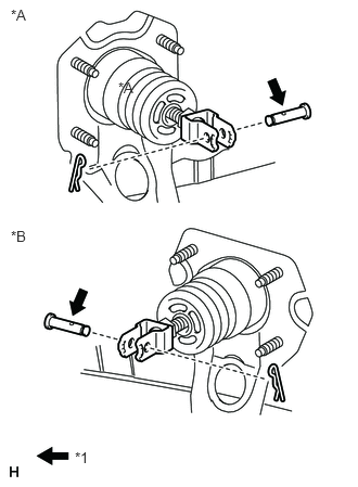
Apply lithium soap base glycol grease to the push rod pin.
Table 3. Text in Illustration *A
for LHD
*B
for RHD
*1
Lithium soap base glycol grease
Connect the brake master cylinder push rod to the brake pedal with the push rod pin and install a new clip as shown in the illustration.
-
INSTALL BRAKE PEDAL RETURN SPRING
-
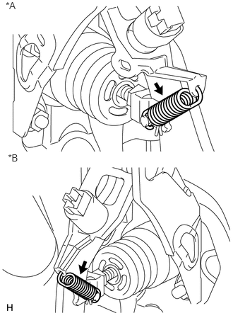
Install the brake pedal return spring between the brake pedal support sub-assembly and brake master cylinder push rod clevis.
Table 4. Text in Illustration *A
for LHD
*B
for RHD
-
INSPECT AND ADJUST BRAKE PEDAL HEIGHT
INSPECT BRAKE PEDAL FREE PLAY
INSPECT BRAKE PEDAL RESERVE DISTANCE
INSTALL LOWER NO. 1 INSTRUMENT PANEL AIRBAG ASSEMBLY
Install the lower No. 1 instrument panel airbag assembly (Click here).
INSTALL UPPER INSTRUMENT PANEL SUB-ASSEMBLY
Install the upper instrument panel sub-assembly (Click here).