FUEL TANK INSTALLATION
PROCEDURE
INSTALL FUEL TANK ASSEMBLY
Set the fuel tank on a transmission jack.
Lift up the transmission jack.
Note:Be careful not to cut the wiring.
-
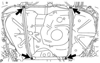
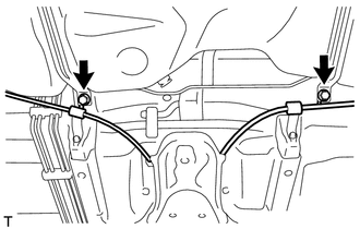
Install the fuel tank with the 2 fuel tank bands with the 4 bolts.
39 N*m
400 kgf*cm
29 ft.*lbf
CONNECT FUEL HOSE
Connect the No. 1 charcoal canister outlet hose.
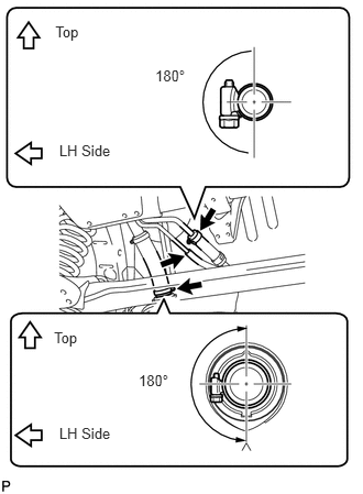
Connect the fuel tank vent hose as shown in the illustration.
Note:Be sure to tighten the hose clamp so that it is at the correct angle.
Connect the fuel tank to filler pipe hose as shown in the illustration.
Note:Be sure to tighten the hose clamp so that it is at the correct angle.
CONNECT FUEL TANK MAIN TUBE SUB-ASSEMBLY
-
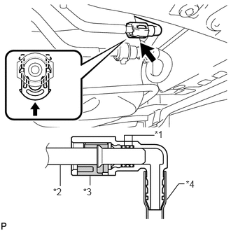
Connect the fuel tank main tube.
Table 1. Text in Illustration *1
O-Ring
*2
Fuel Pipe
*3
Retainer
*4
Nylon Tube
Tip:Push the parts together firmly until a "click" sound is heard.
Note:Before installing the tube connectors to the pipes, check if there is any damage or foreign matter in the connectors.
After the connection, check if the connectors and pipes are securely connected by trying to pull them apart.
-
CONNECT NO. 1 FUEL EVAPORATION TUBE SUB-ASSEMBLY
-
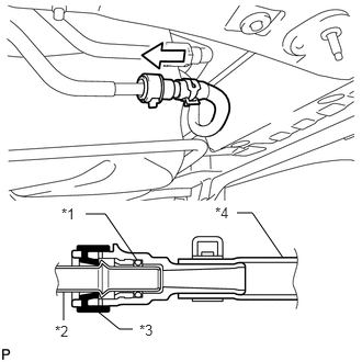
Push the tube connector onto the fuel pipe and install the retainer.
Table 2. Text in Illustration *1
O-Ring
*2
Fuel Pipe
*3
Retainer
*4
Nylon Tube
Note:Check if there is any damage or foreign objects on the connection part of the fuel pipe.
After connecting, check if the fuel pipe and connector are securely connected by pulling on them.
-
CONNECT PARKING BRAKE CABLE
-
Connect the parking brake cable with the 2 bolts.
6.0 N*m
61 kgf*cm
53 in.*lbf
-
INSTALL NO. 1 FUEL TANK PROTECTOR
-
Install the No. 1 fuel tank protector with the 4 clips.
-
INSTALL REAR FLOOR SIDE MEMBER BRACE SUB-ASSEMBLY
-
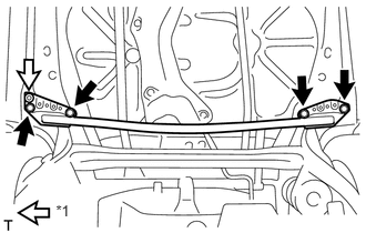
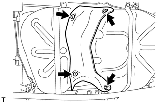
Install the rear floor side member brace with the clip and 4 bolts.
51 N*m
551 kgf*cm
40 ft.*lbf
Table 3. Text in Illustration *1
Clip
-
INSTALL REAR FLOOR SIDE MEMBER COVER RH
-
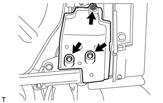
Install the rear floor side member cover with the nut and 2 bolts.
-
INSTALL REAR FLOOR SIDE MEMBER COVER LH
-
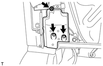
Install the rear floor side member cover with the nut and 2 bolts.
-
INSTALL FRONT FLOOR CENTER COVER LH
-

Install the front floor center cover with the nut and grommet.
Table 4. Text in Illustration *1
Grommet
-
INSTALL FRONT FLOOR CENTER COVER RH
-
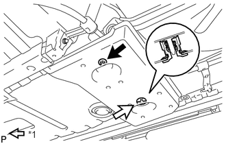
Install the front center floor cover with the nut and grommet.
Table 5. Text in Illustration *1
Grommet
-
INSTALL EXHAUST PIPE ASSEMBLY
Install the exhaust pipe (Click here).
CONNECT FUEL PUMP CONNECTOR
-
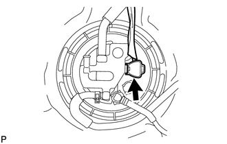
Connect the fuel pump connector.
-
ADD FUEL
INSTALL FUEL TANK CAP ASSEMBLY
CONNECT CABLE TO NEGATIVE BATTERY TERMINAL
Note:When disconnecting the cable, some systems need to be initialized after the cable is reconnected (Click here).
INSPECT FUEL LEAK
INSTALL REAR FLOOR SERVICE HOLE COVER
INSTALL REAR CENTER SEAT ASSEMBLY (w/ REAR CENTER SEAT ASSEMBLY)
Install the rear center seat (Click here).
INSTALL REAR NO. 1 SEAT ASSEMBLY (w/ REAR NO. 1 SEAT ASSEMBLY)
Install the rear No. 1 seat (Click here).