ELECTRONIC CONTROLLED AUTOMATIC TRANSMISSION SYSTEM (for 1GR-FE), Diagnostic DTC:P2772
| DTC Code | DTC Name |
|---|---|
| P2772 | Four Wheel Drive (4WD) Low Switch Circuit Range / Performance |
DESCRIPTION
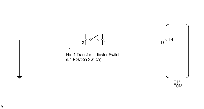
The ECM detects the signal from the No. 1 transfer indicator switch (L4 position switch).
This DTC indicates that the transfer L4 position switch remains ON.
| DTC Code | DTC Detection Condition | Trouble Area |
|---|---|---|
| P2772 |
|
|
MONITOR DESCRIPTION
The ECM monitors the transfer L4 position switch to determine when the transfer-case L4 gear is engaged. If the transfer-case L4 gears remain engaged under all of the following conditions, the ECM will conclude that there is a malfunction of the transfer L4 position switch:
-
The transfer L4 position switch indicates that the L4 transfer-case gears are engaged.
-
Transfer-case shift lever is in the "H" position.
-
Transfer-case output shaft rpm is between 750 and 3,000 rpm.
-
The specified time period has elapsed.
Then the ECM will illuminate the MIL and store the DTC.
WIRING DIAGRAM
INSPECTION PROCEDURE
PROCEDURE
-
INSPECT NO. 1 TRANSFER INDICATOR SWITCH (L4 POSITION SWITCH)
-
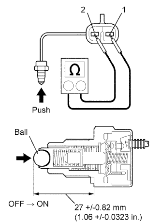
Remove the transfer indicator switch.
-
Measure the resistance of the switch when pushing the ball at the tip of the switch.
Tester Connection Switch Condition Specified Condition 1 - 2 Not pushed 10 kΩ or higher 1 - 2 Pushed Below 1 Ω
NG 
REPLACE NO. 1 TRANSFER INDICATOR SWITCH
OK 
-
-
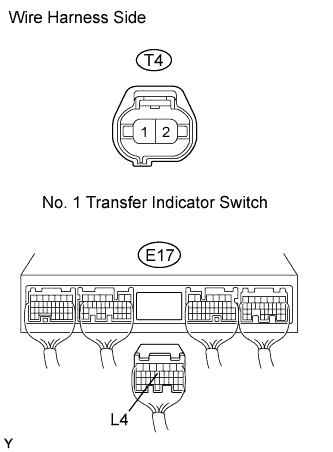
CHECK WIRE HARNESS (NO. 1 TRANSFER INDICATOR SWITCH - ECM)
-
Disconnect the T4 switch connector.
-
Disconnect the E17 ECM connector.
-
Measure the resistance of the wire harness side connectors.
Standard resistance Tester Connection Specified Condition E17-13 (L4) - T4-1 (L4) Below 1 Ω T4-2 (L4) - Body ground Below 1 Ω E17-13 (L4) - Body ground 10 kΩ or higher
NG
REPAIR OR REPLACE HARNESS AND CONNECTOR
OK 
REPLACE ECM
-