NAVIGATION SYSTEM(for HDD), Diagnostic DTC:B15D0
| DTC Code | DTC Name |
|---|---|
| B15D0 | MOST Communication Malfunction |
DESCRIPTION
This DTC is stored when the MOST network connections cannot be established after the master unit is activated.
DTC No. |
Detection Item |
DTC Detection Condition |
Trouble Area |
|---|---|---|---|
B15D0 |
MOST Communication Malfunction |
The MOST network connections cannot be established. |
|
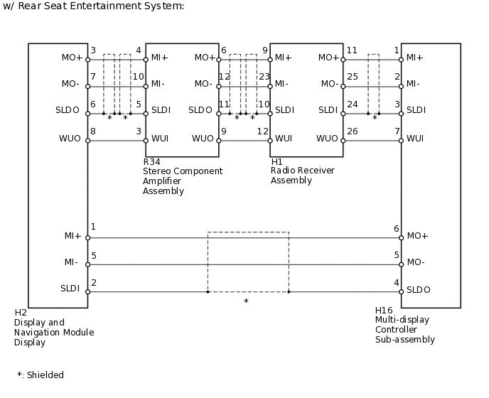
*: w/ Rear Seat Entertainment System
The MOST network connections cannot be established.
Errors may occur in MOST communication between devices due to problems such as electrical noise.
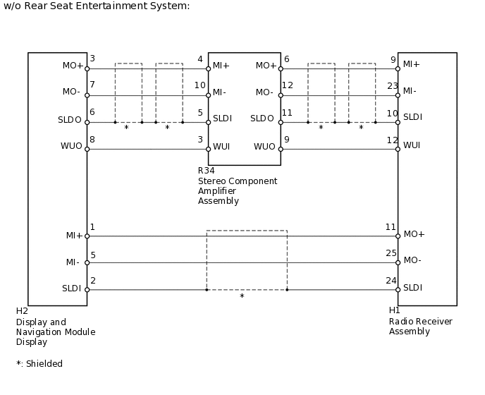
WIRING DIAGRAM
PROCEDURE
CHECK MOST LINE
-
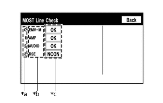
*a
Node position number for devices that use MOST communication
*b
Device Name
*c
Result
Enter "System Check"
Check the result on the "System Check Mode" screen.
Result
Result
Proceed to
"NCON" is displayed for "AMP"
A
"NCON" is displayed for "AUDIO"
B
"NCON" is displayed for "RSE"*
C
"OK" is displayed for all items
D
*: w/ Rear Seat Entertainment System
Tip:When "NCON" is displayed for more than 1 item, proceed to the step for the device that has the smallest node position number.
The "System Check Mode" screen can be displayed only when DTC B15D0 is stored.
B CHECK MOST COMMUNICATION CONNECTORClick here
C CHECK MOST COMMUNICATION CONNECTORClick here
D CHECK HARNESS AND CONNECTOR (DISPLAY AND NAVIGATION MODULE DISPLAY - STEREO COMPONENT AMPLIFIER)Click here
-
CHECK MOST COMMUNICATION CONNECTOR
Check the MOST communication line connector.
Check if the MOST communication line connectors of the display and navigation module display and the stereo component amplifier assembly have any connection problems
Enter the "System Check Mode" screen and check the result
Result
Result
Proceed to
"NCON" is displayed for "AMP"
A
Screen cannot be changed to "MOST Line Check" screen
B
Tip:When the malfunction in the MOST network is repaired, the screen cannot be changed to the "MOST Line Check" screen.
CHECK HARNESS AND CONNECTOR (STEREO COMPONENT AMPLIFIER)
-
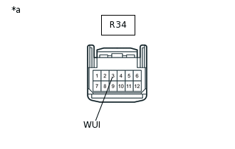
*a
Front view of wire harness connector
(to Stereo Component Amplifier Assembly)
Disconnect the R34 stereo component amplifier assembly connector.
Measure the voltage according to the value(s) in the table below.
Standard Voltage
Tester Connection
Switch Condition
Specified Condition
R34-3 (WUI) - Body ground
Engine switch on (ACC)
4.5 V or higher
Result
Result
OK
NG
-
CHECK HARNESS AND CONNECTOR (STEREO COMPONENT AMPLIFIER - DISPLAY AND NAVIGATION MODULE DISPLAY)
Disconnect the R34 stereo component amplifier assembly connector.
Disconnect the H2 display and navigation module display connector.
Measure the resistance according to the value(s) in the table below.
Standard Resistance
Tester Connection
Condition
Specified Condition
R34-3 (WUI) - H2-8 (WUO)
Always
Below 1 Ω
R34-3 (WUI) - Body ground
Always
10 kΩ or higher
Result
Result
OK
NG
NG REPAIR OR REPLACE HARNESS OR CONNECTOR
CHECK MOST COMMUNICATION CONNECTOR
Check the MOST communication line connector.
Check if the MOST communication line connectors of the stereo component amplifier assembly and radio receiver assembly have any connection problems
Enter the "System Check Mode" screen and check the result
Result
Result
Proceed to
"NCON" is displayed for "AUDIO"
A
Screen cannot be changed to "MOST Line Check" screen
B
Tip:When the malfunction in the MOST network is repaired, the screen cannot be changed to the "MOST Line Check" screen.
CHECK HARNESS AND CONNECTOR (RADIO RECEIVER)
-
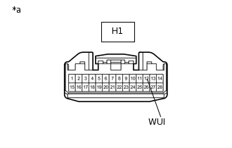
*a
Front view of wire harness connector
(to Radio Receiver Assembly)
Disconnect the H1 radio receiver assembly connector.
Measure the voltage according to the value(s) in the table below.
Standard Voltage
Tester Connection
Switch Condition
Specified Condition
H1-12 (WUI) - Body ground
Engine switch on (ACC)
4.5 V or higher
Result
Result
OK
NG
-
CHECK HARNESS AND CONNECTOR (RADIO RECEIVER - STEREO COMPONENT AMPLIFIER)
Disconnect the H1 radio receiver assembly connector.
Disconnect the R34 stereo component amplifier assembly connector.
Measure the resistance according to the value(s) in the table below.
Standard Resistance
Tester Connection
Condition
Specified Condition
H1-12 (WUI) - R34-9 (WUO)
Always
Below 1 Ω
H1-12 (WUI) - Body ground
Always
10 kΩ or higher
Result
Result
OK
NG
NG REPAIR OR REPLACE HARNESS OR CONNECTOR
CHECK MOST COMMUNICATION CONNECTOR
Check the MOST communication line connector.
Check if the MOST communication line connectors of the radio receiver assembly and multi-display controller sub-assembly have any connection problems
Enter the "System Check Mode" screen and check the result
Result
Result
Proceed to
"NCON" is displayed for "RSE"
A
Screen cannot be changed to "MOST Line Check" screen
B
Tip:When the malfunction in the MOST network is repaired, the screen cannot be changed to the "MOST Line Check" screen.
CHECK HARNESS AND CONNECTOR (MULTI-DISPLAY CONTROLLER)
-
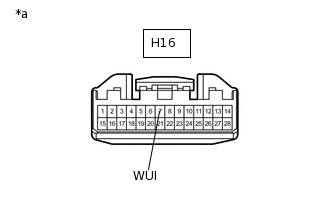
*a
Front view of wire harness connector
(to Multi-display Controller Sub-assembly)
Disconnect the H16 multi-display controller sub-assembly connector.
Measure the voltage according to the value(s) in the table below.
Standard Voltage
Tester Connection
Switch Condition
Specified Condition
H16-7 (WUI) - Body ground
Engine switch on (ACC)
4.5 V or higher
Result
Result
OK
NG
-
CHECK HARNESS AND CONNECTOR (MULTI-DISPLAY CONTROLLER - RADIO RECEIVER)
Disconnect the H16 multi-display controller sub-assembly connector.
Disconnect the H1 radio receiver assembly connector.
Measure the resistance according to the value(s) in the table below.
Standard Resistance
Tester Connection
Condition
Specified Condition
H16-7 (WUI) - H1-26 (WUO)
Always
Below 1 Ω
H16-7 (WUI) - Body ground
Always
10 kΩ or higher
Result
Result
OK
NG
NG REPAIR OR REPLACE HARNESS OR CONNECTOR
CHECK HARNESS AND CONNECTOR (DISPLAY AND NAVIGATION MODULE DISPLAY - STEREO COMPONENT AMPLIFIER)
Disconnect the H2 display and navigation module display connector.
Disconnect the R34 stereo component amplifier assembly connector.
Measure the resistance according to the value(s) in the table below.
Standard Resistance
Tester Connection
Condition
Specified Condition
H2-3 (MO+) - R34-4 (MI+)
Always
Below 1 Ω
H2-7 (MO-) - R34-10 (MI-)
Always
Below 1 Ω
H2-6 (SLDO) - R34-5 (SLDI)
Always
Below 1 Ω
H2-3 (MO+) - Body ground
Always
10 kΩ or higher
H2-7 (MO-) - Body ground
Always
10 kΩ or higher
H2-6 (SLDO) - Body ground
Always
10 kΩ or higher
Result
Result
OK
NG
NG REPAIR OR REPLACE HARNESS OR CONNECTOR
CHECK HARNESS AND CONNECTOR (STEREO COMPONENT AMPLIFIER - RADIO RECEIVER)
Disconnect the R34 stereo component amplifier assembly connector.
Disconnect the H1 radio receiver assembly connector.
Measure the resistance according to the value(s) in the table below.
Standard Resistance
Tester Connection
Condition
Specified Condition
R34-6 (MO+) - H1-9 (MI+)
Always
Below 1 Ω
R34-12 (MO-) - H1-23 (MI-)
Always
Below 1 Ω
R34-11 (SLDO) - H1-10 (SLDI)
Always
Below 1 Ω
R34-6 (MO+) - Body ground
Always
10 kΩ or higher
R34-12 (MO-) - Body ground
Always
10 kΩ or higher
R34-11 (SLDO) - Body ground
Always
10 kΩ or higher
Result
Result
Proceed to
OK (w/ Rear Entertainment System)
A
OK (w/o Rear Entertainment System)
B
NG
C
B CHECK HARNESS AND CONNECTOR (RADIO RECEIVER - DISPLAY AND NAVIGATION MODULE DISPLAY)Click here
C REPAIR OR REPLACE HARNESS OR CONNECTOR
CHECK HARNESS AND CONNECTOR (RADIO RECEIVER - MULTI-DISPLAY CONTROLLER)
Disconnect the H1 radio receiver assembly connector.
Disconnect the H16 multi-display controller sub-assembly connector.
Measure the resistance according to the value(s) in the table below.
Standard Resistance
Tester Connection
Condition
Specified Condition
H1-11 (MO+) - H16-1 (MI+)
Always
Below 1 Ω
H1-25 (MO-) - H16-2 (MI-)
Always
Below 1 Ω
H1-24 (SLDI) - H16-3 (SLDI)
Always
Below 1 Ω
H1-11 (MO+) - Body ground
Always
10 kΩ or higher
H1-25 (MO-) - Body ground
Always
10 kΩ or higher
H1-24 (SLDI) - Body ground
Always
10 kΩ or higher
Result
Proceed to
OK
NG
NG REPAIR OR REPLACE HARNESS OR CONNECTOR
CHECK HARNESS AND CONNECTOR (MULTI-DISPLAY CONTROLLER - DISPLAY AND NAVIGATION MODULE DISPLAY)
Disconnect the H16 multi-display controller sub-assembly connector.
Disconnect the H2 display and navigation module display connector.
Measure the resistance according to the value(s) in the table below.
Standard Resistance
Tester Connection
Condition
Specified Condition
H16-6 (MO+) - H2-1 (MI+)
Always
Below 1 Ω
H16-5 (MO-) - H2-5 (MI-)
Always
Below 1 Ω
H16-4 (SLDO) - H2-2 (SLDI)
Always
Below 1 Ω
H16-6 (MO+) - Body ground
Always
10 kΩ or higher
H16-5 (MO-) - Body ground
Always
10 kΩ or higher
H16-4 (SLDO) - Body ground
Always
10 kΩ or higher
Result
Proceed to
OK
NG
NG REPAIR OR REPLACE HARNESS OR CONNECTOR
CHECK FOR DTC
Clear the DTCs.
Body Electrical > Navigation System > Clear DTCs
Check for DTCs and check if the same trouble occurs again.
Body Electrical > Navigation System > Trouble Codes
OK
No DTCs are output.
Result
Proceed to
OK
NG
CHECK HARNESS AND CONNECTOR (RADIO RECEIVER - DISPLAY AND NAVIGATION MODULE DISPLAY)
Disconnect the H1 radio receiver assembly connector.
Disconnect the H2 display and navigation module display assembly connector.
Measure the resistance according to the value(s) in the table below.
Standard Resistance
Tester Connection
Condition
Specified Condition
H1-11 (MO+) - H2-1 (MI+)
Always
Below 1 Ω
H1-25 (MO-) - H2-5 (MI-)
Always
Below 1 Ω
H1-24 (SLDI) - H2-2 (SLDI)
Always
Below 1 Ω
H1-11 (MO+) - Body ground
Always
10 kΩ or higher
H1-25 (MO-) - Body ground
Always
10 kΩ or higher
H1-24 (SLDI) - Body ground
Always
10 kΩ or higher
Result
Proceed to
OK
NG
NG REPAIR OR REPLACE HARNESS OR CONNECTOR
CHECK FOR DTC
Clear the DTCs.
Body Electrical > Navigation System > Clear DTCs
Check for DTCs and check if the same trouble occurs again.
Body Electrical > Navigation System > Trouble Codes
OK
No DTCs are output.
Result
Proceed to
OK
NG